LiftMaster MJ MJ5011E Installation-2008 Manual - Page 23
Diagram, Diagnostic Led Table
 |
View all LiftMaster MJ manuals
Add to My Manuals
Save this manual to your list of manuals |
Page 23 highlights
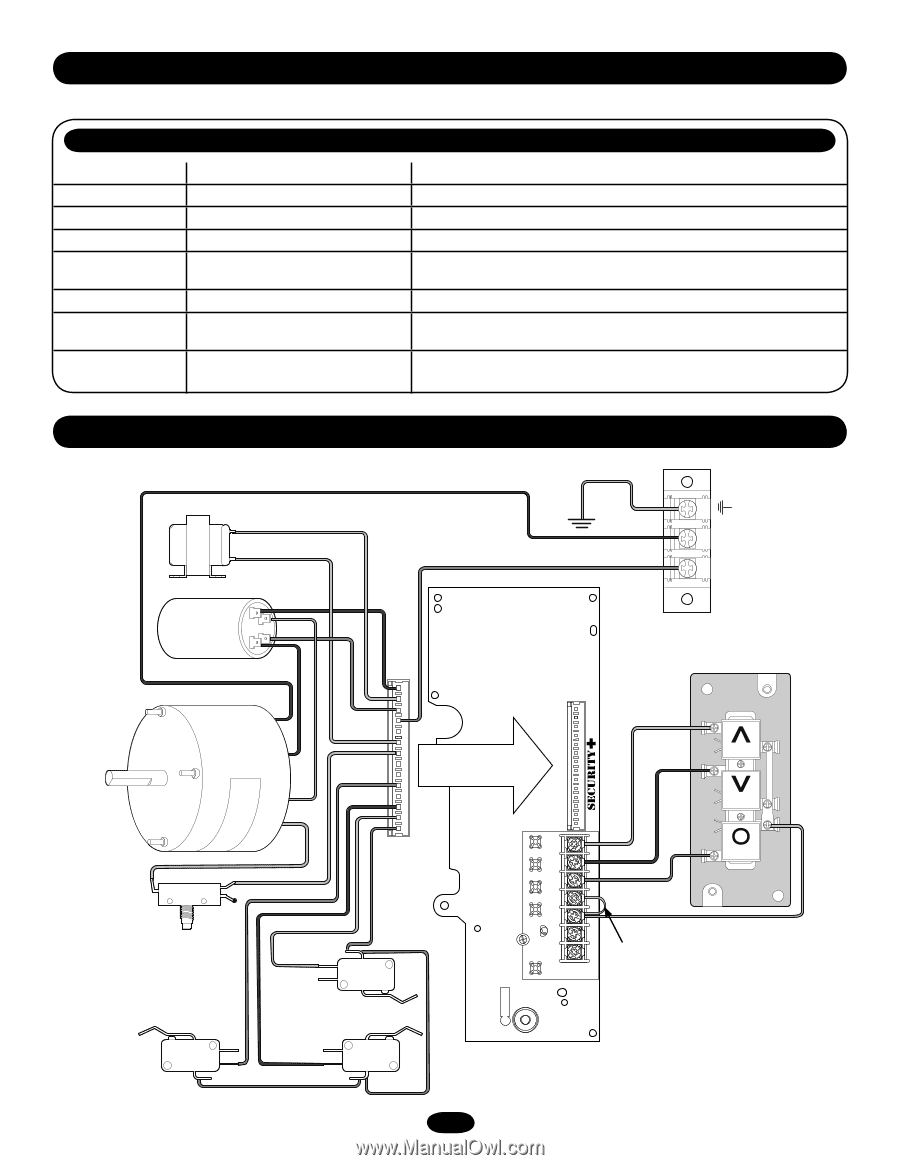
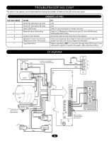
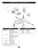
TROUBLESHOOTING CONT. The status of the operator can be determined by counting the number of flashes of the LED on the logic board. # OF LED FLASHES 1 2 3 4 5 6 7 DIAGNOSTIC LED TABLE STATUS System OK. Operating in C2 mode System OK. Operating in B2 mode Stuck CLOSE button Monitored Safety Device failure Incorrect motor direction Maximum run timer has timed out (Maximum run time = 90 seconds) Logic Board Failure FIX none none Check for stuck close button or shorted close wire Check for: 1) Misaligned or blocked photo eyes. 2) Issue with Monitored Sensing Edge and/or wiring. Reverse the yellow and red motor wires on the capacitor. Check clutch adjustment. Door height or speed may exceed the range the operator can travel. Call Technical Support for assistance. Replace Logic Board. NOTE: It is normal for the logic board LED to flash 7 times when power is applied or cycled to the operator. (Not a logic board failure.) DIAGRAM Brake (Optional) Blue* Blue* * If brake is not supplied, wires are capped separately Green Black Black L2 L1 Capacitor Yellow Red Yellow Red Motor ** If interlock is not used, wires are capped together. Interlock Brown** Brown** Orange Purple Yellow Grey Safety Limit Switch Open Limit Switch Grey Close Limit Switch 23 AANTUX ANT J2 TTC LEARN STOP CLOSE OPEN LED 1 2 3 45 6 7 LMEP1 LMEP2 COM INTRLK STOP CLOSE OPEN OPEN CLOSE STOP Remove Jumper to install external door interlock.
-
 1
1 -
2
-
3
-
4
-
5
-
6
-
7
-
8
-
9
-
10
-
11
-
12
-
13
-
14
-
15
-
16
-
17
-
 18
18 -
 19
19 -
 20
20 -
 21
21 -
 22
22 -
 23
23 -
 24
24 -
 25
25 -
 26
26 -
 27
27 -
 28
28 -
29
-
30
-
31
-
32
 |
 |