LiftMaster MJ MJ5011E Installation-2008 Manual - Page 32
Control Connection Diagram, IMPORTANT NOTES - chamberlain
 |
View all LiftMaster MJ manuals
Add to My Manuals
Save this manual to your list of manuals |
Page 32 highlights
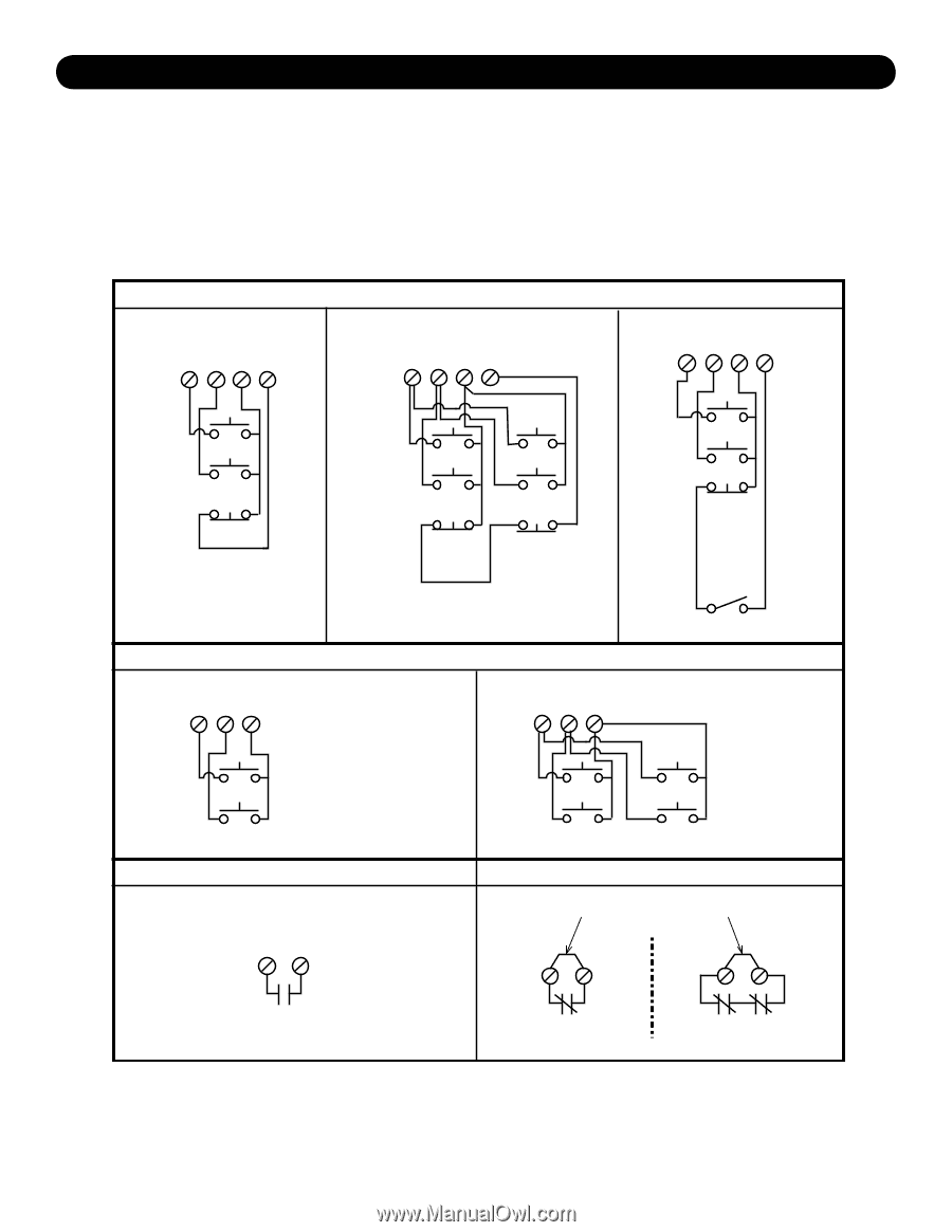
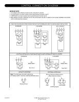
CONTROL CONNECTION DIAGRAM IMPORTANT NOTES: 1. The 3-Button Control Station provided must be connected for operation. 2. If a STOP button is not used, a jumper must be placed between terminals 3 and 5. 3. If INTERLOCK is not used a jumper must be placed between terminals 3 and 4. 4. When adding accessories, install them one at a time and test each one after it is added to ensure proper installation and operation with the Commercial Door Operator. 3 BUTTON STATION OR 3 POSITION KEYSWITCH WITH SPRING RETURN TO CENTER AND STOP BUTTON STANDARD 2 OR MORE KEY LOCKOUT 7635 7635 7635 Open Close Stop Open Close Stop Open Close Stop Open Close Stop Keyswitch 2 BUTTON STATION OR 3 POSITION KEYSWITCH WITH SPRING RETURN TO CENTER STANDARD 763 763 2 OR MORE Open Close C2 MODE ONLY See note 2. DEVICE TO REVERSE Note: For photo-eyes connection options see OPTIONAL SAFETY DEVICE CONFIGURATION section. 12 Open Close Open Close C2 MODE ONLY See note 2. EXTERNAL INTERLOCK Remove Factory Installed Jumper When Interlock is Used 3 4 3 4 Sensing Device ONE 2 OR MORE All Wiring Types 01-34217C © 2009, The Chamberlain Group, Inc. All Rights Reserved
-
 1
1 -
2
-
3
-
4
-
5
-
6
-
7
-
8
-
9
-
10
-
11
-
12
-
13
-
14
-
15
-
16
-
17
-
18
-
19
-
20
-
21
-
22
-
23
-
24
-
25
-
26
-
 27
27 -
 28
28 -
 29
29 -
 30
30 -
 31
31 -
 32
32
 |
 |