LiftMaster Miracle-One MIRACLE ONE Manual - Page 16
Removing The Control/surge Boards - battery
 |
View all LiftMaster Miracle-One manuals
Add to My Manuals
Save this manual to your list of manuals |
Page 16 highlights
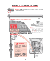
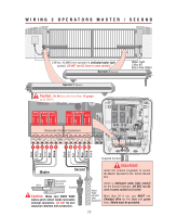
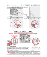
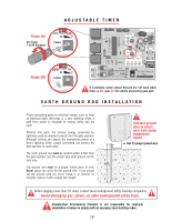
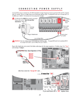
REMOVING THE CONTROL / SURGE BOARDS 1 Unscrew the 4 Phillips head screws from the cover. 2 Unplug the J1 and J3 plugs. 1 1 3 Unplug battery connector. 4 Unplug all accessory wires from Surge Suppressor's removable terminals. 5 Disconnect ground wire. 6 Remove three Phillips screws from control board and remove board. 7 Remove three Phillips screws from surge suppressor board and remove board. 8 BLACK WHITE RED BROWN BLUE GREEN BLACK WHITE RED BROWN BLUE GREEN BURGLAR ALARM INPUT UL SENSOR CENTER LOOP SAFETY LOOP EXIT LOOP GROUND RADIO +24 VOLT +24 VAC INPUT BLACK WHITE RED BROWN BLUE GREEN BLACK WHITE RED BROWN BLUE GREEN BURGLAR ALARM INPUT UL SENSOR CENTER LOOP SAFETY LOOP EXIT LOOP GROUND RADIO +24 VOLT +24 VAC INPUT MIRACLE SURGE PROTECTION MIRACLE SURGE PROTECTION 1 3 REV A 2 ® LAKE FOREST, CALIFORNIA www.eliteaccess.com 2 SINGLE OR MASTER ONLY MOTOR BRAKE LIMITS 12 3 456 SLAVE ONLY MOTOR BRAKE LIMITS 7 8 9 10 11 12 13 14 15 16 17 18 19 20 21 22 23 24 25 26 27 5 MAGLOCK ALARM SYSTEM ON REVERSE SENSOR ALARM SENSOR STOP BY POSITIVE STOP OPEN INSIDE NO OFF 60 OPEN OUTSIDE YES ON 3 TIMER CENTRAL POWER CHARGE OK BATTERY LOW CONTROL STRIKE OPEN SAFETY LOOP RADIO REC CENTER LOOP WRHEEPNLALCEEDFISUSOEN ® ACCESS SYSTEMS INC 6 ® LAKE FOREST, CALIFORNIA www.eliteaccess.com REV A SINGLE OR MASTER ONLY MOTOR BRAKE LIMITS 12 3 456 SLAVE ONLY MOTOR BRAKE LIMITS 7 8 9 10 11 12 13 14 15 16 17 18 19 20 21 22 23 24 25 26 27 7 44 MOUNTING THE CONTROL BOX Caution: Do Not make new mounting holes, or enlarge existing holes in control box. Use the four mounting holes provided. Remove the four nuts and remove battery rack. Reverse this process to reinstall. 15 Mount control box with four screws and washers (recommend #10 thru 1/4-20 Bolts or Screws) Do Not over tighten.
-
 1
1 -
2
-
3
-
4
-
5
-
6
-
7
-
8
-
9
-
10
-
 11
11 -
 12
12 -
 13
13 -
 14
14 -
 15
15 -
 16
16 -
 17
17 -
 18
18 -
 19
19 -
 20
20 -
 21
21 -
22
-
23
-
24
-
25
-
26
-
27
-
28
-
29
-
30
-
31
-
32
-
33
-
34
-
35
-
36
-
37
-
38
-
39
-
40
-
41
-
42
-
43
-
44
-
45
-
46
-
47
-
48
-
49
 |
 |
