LiftMaster Miracle-One MIRACLE ONE Manual - Page 22
Wiring Additional Inputs - elite gate opener
 |
View all LiftMaster Miracle-One manuals
Add to My Manuals
Save this manual to your list of manuals |
Page 22 highlights
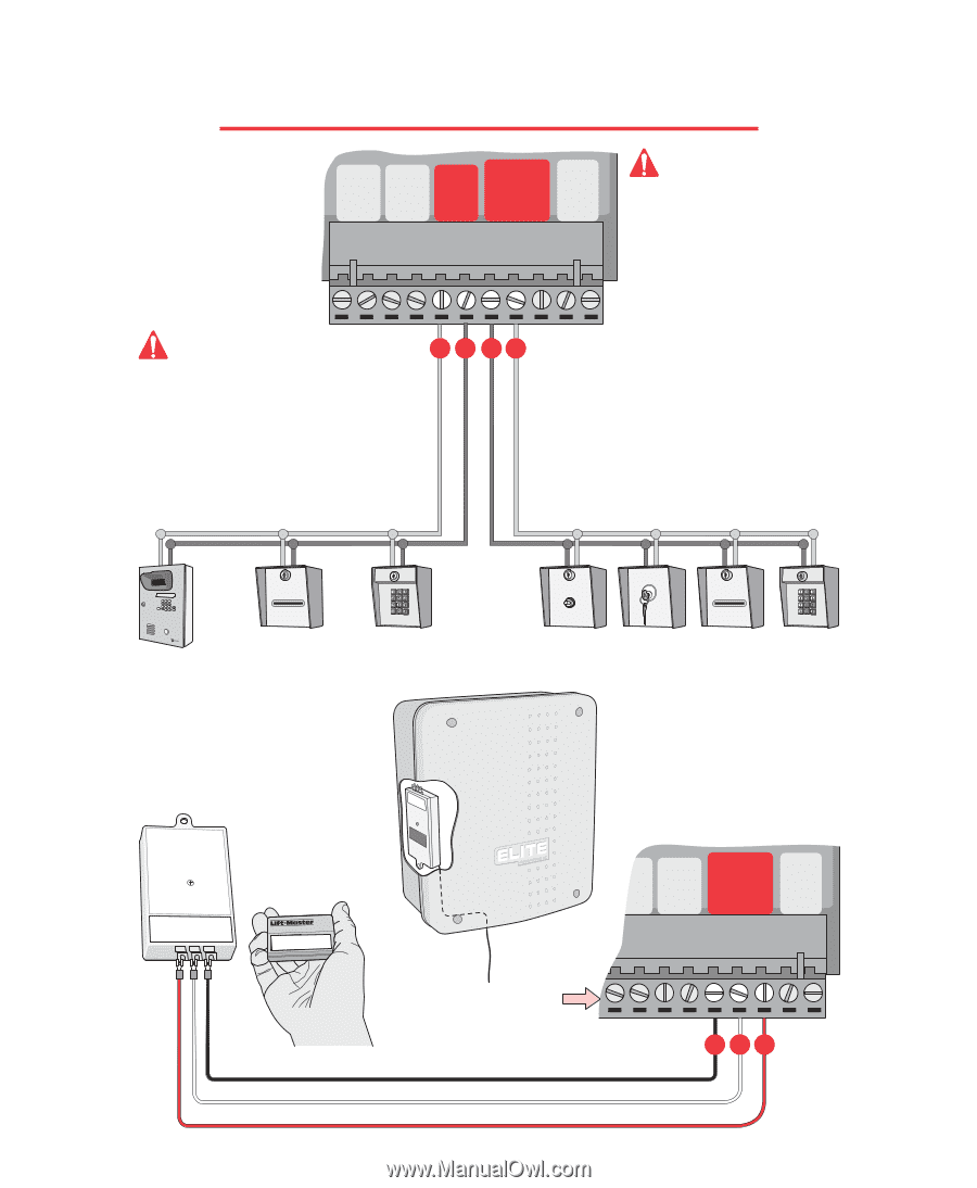
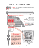
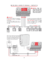
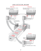
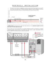
BLACK WHITE RED BROWN BLUE GREEN BURGLAR ALARM INPUT UL SENSOR CENTER LOOP SAFETY LOOP STRIKE INPUT GROUND RADIO +24 VOLT +24 VAC INPUT WIRING ADDITIONAL INPUTS SLAVE ONLY MOTOR BRAKE LIMITS 7 8 9 10 11 12 13 14 15 16 17 18 19 20 21 22 23 24 25 26 27 Removable Terminal Connectors Caution: Make sure BARE WIRE makes good contact inside removable terminal connectors. DO NOT let wire insulation interfere with connection. MIRACLE SURGE PROTECTION Important: Wiring at #21 and #22 will be recognized as an Open Only command, and Will Not close the gate. To automatically Close the gate after an open cycle, the control board timer must be turned ON. 21 22 23 24 ® LAKE FOREST, CALIFORNIA www.eliteaccess.com Works as "Open Only" command To provide a close command use #23 and #24. Wiring at #23 and #24 will be recognized as a Three Push Button command. The First command will open the gate. The Second command will stop the gate. The Third command will close the gate. Works as "3 Push Button" control 123 456 789 HELP 0 REV A Elite Entry Phone Card Reader Digital Lock Push Button Key Switch Card Reader Digital Lock Mount receiver inside the control board box as shown using velcro. Note that the receiver is mounted upside down so the antenna can fit through the hole at the bottom of the control board box. BLACK WHITE RED BROWN BLUE GREEN BLACK WHITE RED BROWN BLUE GREEN BURGLAR ALARM INPUT UL SENSOR CENTER LOOP SAFETY LOOP STRIKE INPUT GROUND RADIO +24 VOLT +24 VAC INPUT SINGLE OR MASRTaERdOioNLY MOTOR BRARKeE ceLivIMeITrS 12 3 456 3 21 SLAVE ONLY MOTOR BRAKE LIMITS 7 8 9 10 11 12 ® 13 14 15 16 17 18 19 20 21 22 23 24 25 26 27 Removable Terminal Connector 1 (24V) / Ground 2 (Relay) 3 (Radio Power) / +24V Black White Red 21 23 24 25
-
 1
1 -
2
-
3
-
4
-
5
-
6
-
7
-
8
-
9
-
10
-
11
-
12
-
13
-
14
-
15
-
16
-
 17
17 -
 18
18 -
 19
19 -
 20
20 -
 21
21 -
 22
22 -
 23
23 -
 24
24 -
 25
25 -
 26
26 -
 27
27 -
28
-
29
-
30
-
31
-
32
-
33
-
34
-
35
-
36
-
37
-
38
-
39
-
40
-
41
-
42
-
43
-
44
-
45
-
46
-
47
-
48
-
49
 |
 |