LiftMaster Miracle-One MIRACLE ONE Manual - Page 47
Surge Suppressor Wiring Diagram, 888-elite-10
 |
View all LiftMaster Miracle-One manuals
Add to My Manuals
Save this manual to your list of manuals |
Page 47 highlights
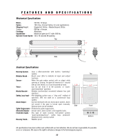
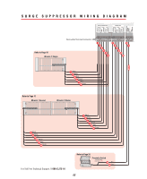
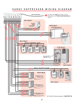
SURGE SUPPRESSOR WIRING DIAGRAM Refer to Page 16 Miracle 1 Single BLACK WHITE RED BROWN BLUE GREEN BLACK WHITE RED BROWN BLUE GREEN BURGLAR ALARM INPUT UL SENSOR SINGLE OR MASTER ONLY MOTOR BRAKE LIMITS 123456 SECOND ONLY MOTOR BRAKE LIMITS 7 8 9 10 11 12 13 14 15 16 Removable Terminal Connectors 1 2 3 4 5 6 7 8 9 10 11 12 13 14 Ground Refer to Page 17 Miracle 1 Second 1 Black 2 White 3 Red 4 Brown 5 Blue 6 Green Miracle 1 Master 7 Black 8 White 9 Red 10 Brown 11 Blue 12 Green 1 Black 2 White 3 Red 4 Brown 5 Blue 6 Green For Toll Free Technical Support: 1-888-ELITE-10 Refer to Page 31 Proximity Switch Normally Open Elite Part # A PRS 13 N.O. 14 Com 46
-
 1
1 -
2
-
3
-
4
-
5
-
6
-
7
-
8
-
9
-
10
-
11
-
12
-
13
-
14
-
15
-
16
-
17
-
18
-
19
-
20
-
21
-
22
-
23
-
24
-
25
-
26
-
27
-
28
-
29
-
30
-
31
-
32
-
33
-
34
-
35
-
36
-
37
-
38
-
39
-
40
-
41
-
 42
42 -
 43
43 -
 44
44 -
 45
45 -
 46
46 -
 47
47 -
 48
48 -
 49
49
 |
 |

46
SURGE SUPPRESSOR WIRING DIAGRAM
Miracle 1 Second
Miracle 1 Master
Miracle 1 Single
BLACK
MOTOR
WHITE
RED
BRAKE
SINGLE OR MASTER ONLY
SECOND ONLY
BROWN
BLUE
LIMITS
GREEN
BLACK
MOTOR
WHITE
RED
BRAKE
BROWN
BLUE
LIMITS
GREEN
BURGLAR
ALARM
INPUT
UL
SENSOR
1
2
3
4
5
6
7
8
9
10
11 12
13
14
15 16
Green
Blue
Brown
Red
White
Black
1
2
3
4
5
6
1
2
3
4
5
6
Green
Blue
Brown
Red
White
Black
1
2
3
4
5
6
Green
Blue
Brown
Red
White
Black
7
8
9
10
11
12
13
14
Proximity Switch
Normally Open
Elite Part #
A PRS
Refer to Page 31
Refer to Page 16
Refer to Page 17
7
8
9
10
11
12
13
14
Removable Terminal Connectors
Com
N.O.
Ground
For Toll Free Technical Support:
1-888-ELITE-10