LiftMaster Miracle-One MIRACLE ONE Manual - Page 30
SURGE SUPPRESSOR BOARD DESCRIPTION, Green Ground Wire, Master/Second J1, Surge Suppressor, Plug Shown
 |
View all LiftMaster Miracle-One manuals
Add to My Manuals
Save this manual to your list of manuals |
Page 30 highlights
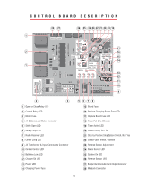
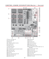
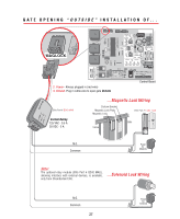
SURGE SUPPRESSOR BOARD DESCRIPTION MIRACLE SURGE PROTECTION Master/Second J1 Surge Suppressor REV A Plug Shown ® LAKE FOREST, CALIFORNIA www.eliteaccess.com J3 Plug Battery Plug BLACK WHITE RED BROWN BLUE GREEN BLACK WHITE RED BROWN BLUE GREEN BURGLAR ALARM INPUT UL SENSOR CENTER LOOP SAFETY LOOP STRIKE INPUT GROUND RADIO +24 VOLT +24 VAC INPUT SINGLE OR MASTER ONLY MOTOR BRAKE LIMITS 12 3 456 SECOND ONLY MOTOR BRAKE LIMITS 7 8 9 10 11 12 13 14 15 16 17 18 19 20 21 22 23 24 25 26 27 Green Ground Wire 2 4 6 7 9 11 13 15 17 19 21 23 25 27 1 3 5 - 8 10 12 14 16 18 20 22 24 26 Removable Terminal Connectors 1 Black Wire from Operator (Power) 2 White Wire from Operator (Power) 3 Red Wire from Operator (Brake) 4 Brown Wire from Operator (Brake) 5 Blue Wire from Operator (Limits) Single or Master Operator Only 6 Green Wire from Operator (Limits) 7 Black Wire from Operator (Power) 8 White Wire from Operator (Power) 9 Red Wire from Operator (Brake) 10 Brown Wire from Operator (Brake) 11 Blue Wire from Operator (Limits) Second Operator Only 12 Green Wire from Operator (Limits) 13 Burglar Alarm Input (Normally Open) 14 Burglar Alarm Input (Common) 15 UL Sensor Input (Normally Open) 16 UL Sensor Input (Common) 17 Center Loop (Normally Open) 18 Center Loop (Common) 19 Safety Loop (Normally Open) 20 Safety Loop (Common) 21 Strike Input (Normally Open) 22 Strike Input (Common) 23 Ground (Common) 24 Radio Relay Input 25 Radio Input (+ 24 Volt DC) 26 AC Power Input +24 VAC (Polarity does not matter) 27 AC Power Input +24 VAC (Polarity does not matter) 29
-
 1
1 -
2
-
3
-
4
-
5
-
6
-
7
-
8
-
9
-
10
-
11
-
12
-
13
-
14
-
15
-
16
-
17
-
18
-
19
-
20
-
21
-
22
-
23
-
24
-
 25
25 -
 26
26 -
 27
27 -
 28
28 -
 29
29 -
 30
30 -
 31
31 -
 32
32 -
 33
33 -
 34
34 -
 35
35 -
36
-
37
-
38
-
39
-
40
-
41
-
42
-
43
-
44
-
45
-
46
-
47
-
48
-
49
 |
 |
