MSI Z77 User Guide - Page 40
damage.
 |
View all MSI Z77 manuals
Add to My Manuals
Save this manual to your list of manuals |
Page 40 highlights
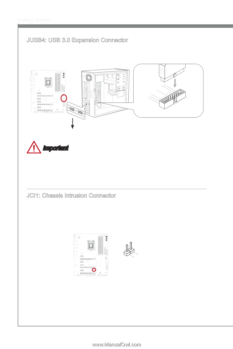
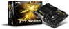
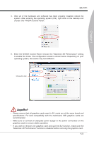
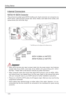
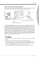
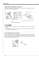
Getting Started JUSB4: USB 3.0 Expansion Connector The USB 3.0 port is backwards compatible with USB 2.0 devices. It supports data transfer rates up to 5Gbits/s (SuperSpeed). 115V 111.U2S1.U3B1S.2G4B.1.0rU25o+..Su10Un6B-S1d.3G7B_1.r3TU8o1_X.uSU9Tn_B.2XSdCP30_Bo__.C3NwDR__oePXRDrP_XNDin_PDN 109.G.U8roS. Uu7Bn.S2G6d.B.r0Uo25+Su..0Un4B-d.S3G3B_.rT3Uo2X_uS.UT1_nB.XCdSP3_B__oCD3Rw__PXeDRr_NXD_PDN * The MB layout in this figure is for reference only. USB 3.0 Bracket (optional) Important • Note that the VCC and GND pins must be connected correctly to avoid possible damage. • To use a USB 3.0 device, you must connect the device to a USB 3.0 port through an optional USB 3.0 compliant cable. JCI1: Chassis Intrusion Connector This connector connects to the chassis intrusion switch cable. If the computer case is opened, the chassis intrusion mechanism will be activated. The system will record this intrusion and a warning message will flash on screen. To clear the warning, you must enter the BIOS utility and clear the record. 1.C2.IGNTroRuUnd 1-28
-
 1
1 -
2
-
3
-
4
-
5
-
6
-
7
-
8
-
9
-
10
-
11
-
12
-
13
-
14
-
15
-
16
-
17
-
18
-
19
-
20
-
21
-
22
-
23
-
24
-
25
-
26
-
27
-
28
-
29
-
30
-
31
-
32
-
33
-
34
-
 35
35 -
 36
36 -
 37
37 -
 38
38 -
 39
39 -
 40
40 -
 41
41 -
 42
42 -
 43
43 -
 44
44 -
 45
45 -
46
-
47
-
48
-
49
-
50
-
51
-
52
-
53
-
54
-
55
-
56
-
57
-
58
-
59
-
60
-
61
-
62
-
63
-
64
-
65
-
66
-
67
-
68
-
69
-
70
-
71
-
72
-
73
-
74
-
75
-
76
-
77
-
78
-
79
-
80
-
81
-
82
-
83
-
84
-
85
-
86
-
87
-
88
-
89
-
90
-
91
-
92
-
93
-
94
-
95
-
96
-
97
-
98
-
99
-
100
 |
 |