Marantz PM-11S1 PM-11S1 User Manual - Page 13
Display
 |
View all Marantz PM-11S1 manuals
Add to My Manuals
Save this manual to your list of manuals |
Page 13 highlights
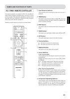
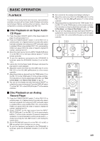
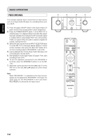
NAMES AND FUNCTIONS OF PARTS !1 PRE OUT Button This button turns output from the PRE OUT jack on the rear panel ON and OFF. When output is ON, the center of the button is lit a blue color. !2 REC OUT Button This button turns the signals output from the RECORDER 1 and 2 OUT jacks on the rear panel ON and OFF. When output is ON, the center of the button is lit a blue color. For instructions on how to record, see "RECORDING" on pg. 14. When RECORDER 1 is selected as the input source, signals are not output to the RECORDER 1 OUT jack. The same goes for the RECORDER 2 OUT jack when RECORDER 2 is selected as the input source. !3 PHONO MC Button This button switches the phono equalizer between MC and MM. When MC is set, the center of the button is lit a blue color. Set the phono equalizer amplifier according to the type of cartridge you use. !4 Side Illumination The side illumination casts a blue light over switches and buttons. It can be turned ON and OFF from the DISPLAY button. For instructions on how to operate the side illumination, see "HOW TO OPERATE THE SIDE ILLUMINATION" on pg. 16. DISPLAY OPERATE !5 Power Indicator This indicator is lit a blue color while power to the PM11S1 is ON. !6 Display Panel Approximately 3 seconds after power to the PM-11S1 is activated, the ID set for the PM-11S1 is displayed here. After that, the top line displays the input source selected with either the INPUT SELECTOR knob or the remote controller, while the bottom line displays the volume level set with the VOLUME knob or the remote controller. When the PM-11S1 I is first activated, the attenuation level (dB) is displayed for the initial volume level. Volume Level Indication Max Turn the VOLUME knob on the PM-11S1 to the right or press the VOLUME 3 button on the remote controller. 0.5 dB steps Turn the VOLUME knob on the PM-11S1 to the left or press the VOLUME 4 button on the remote controller. Min The display panel also displays left-right level balance and tone control trimming level. For instructions on how to adjust bass and treble, see "How to Trim Bass" and "How to Trim Treble" on pg. 18. The display panel also displays messages in response to PM-11S1 operation. !7 OPERATE Indicator This indicator indicates the operating status of the PM11S1. When the ID is set to "0" for standalone operation, it is lit a red color. When multiple PM-11S1s are connected by FCBS, only the OPERATE indicator of the master PM11S1 (ID 1) lights a red color. Slave PM-11S1s whose OPERATE indicator does not light a red color cannot be used to operate other units in sync. For more information on the FCBS, see "ABOUT FCBS" on pg. 15. Also, the OPERATE indicator flashes if a protective circuit trips. For troubleshooting procedures, see "TROUBLESHOOTING" on pg. 20. 9 ENGLISH
-
 1
1 -
2
-
3
-
4
-
5
-
6
-
7
-
 8
8 -
 9
9 -
 10
10 -
 11
11 -
 12
12 -
 13
13 -
 14
14 -
 15
15 -
 16
16 -
 17
17 -
 18
18 -
19
-
20
-
21
-
22
-
23
-
24
-
25
-
26
-
27
 |
 |
