Marantz PM-11S1 PM-11S1 User Manual - Page 19
How To Use And Set Features
 |
View all Marantz PM-11S1 manuals
Add to My Manuals
Save this manual to your list of manuals |
Page 19 highlights
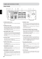
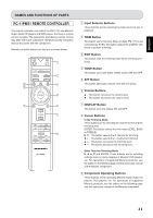
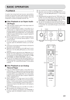
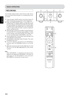
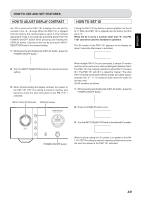
ENGLISH HOW TO USE AND SET FEATURES ABOUT FCBS FCBS is short for Floating Control Bus System. It is a communication system that connects up to four PM-11S1s over a dedicated bus line so as to enable synchronized operations amongst them via 2-way data communications. The FCBS connections can be made with either of the below two types of portable audio connection cable. Prepare the number of connection cables for the number of PM-11S1s to connect. • Connection cable with monaural ⇔ monaural miniplugs • Connection cable with stereo ⇔ stereo miniplugs Resistor connection cables are sold commercially, but they cannot be used with the PM-11S1. The below figure is an example of four PM-11S1s connected by FCBS. The top PM-11S1 is the master unit of ID 1 and controls the three slave units of IDs 2 - 4. When the master PM-11S1 is operated, the input source, volume level, ATT feature, display and tone control ON/OFF feature of slave PM11S1s are interlocked to the master unit. This function can be applied to various usages such as complete-bi-amp with 2 PM-11S1s, and 5.1ch multi-channel with 3 PM-11S1s. To turn power to multiple FCBS-connected PM-11S1s ON/ OFF, activate power in the order of lowest to highest ID number and deactivate power in order of highest to lowest ID number. Master PM-11S1 ... ID 1 ABOUT THE BI-AMP MODE The PM-11S1 is equipped with a bi-amp mode to enable a complete bi-amp connection using two PM-11S1s. This complete bi-amp connection is a high-end technique for enhancing sound quality, proposed by Marantz. With it, the biamp supporting speaker system is separated from the preamplifiers that separately drive the low and high speakers. (For more information, see Connection Example 3.) The bi-amp mode is engaged by setting the operating mode switch on the rear panel to "BI-AMP". In the bi-amp mode, the signals input to the L channel are passed through the input buffer amplifier, split by the input selector and transferred to the left and right volume amplifiers. After that, the signals are sequentially sent to the left and right voltage amplifiers and the left and right power amplifiers, and ultimately output to the speaker output terminals. In the biamp mode, the R channel input jacks cannot be used. The below figure shows example displays in the stereo and bi-map modes. Stereo mode Bi-amp mode Note Turn power to the PM-11S1 OFF before changing the operating mode switch setting. Turning the power ON again activates the new setting. Slave PM-11S1 ... ID 2 Slave PM-11S1 ... ID 3 Slave PM-11S1 ... ID 4 15
-
 1
1 -
2
-
3
-
4
-
5
-
6
-
7
-
8
-
9
-
10
-
11
-
12
-
13
-
 14
14 -
 15
15 -
 16
16 -
 17
17 -
 18
18 -
 19
19 -
 20
20 -
 21
21 -
 22
22 -
 23
23 -
 24
24 -
25
-
26
-
27
 |
 |
