Maytag MGR5751BDQ Installation Manual - Page 8
Air Shutter - Oven Burner, Removing Sealed Burner For Adjustment Or, Service - parts
 |
View all Maytag MGR5751BDQ manuals
Add to My Manuals
Save this manual to your list of manuals |
Page 8 highlights
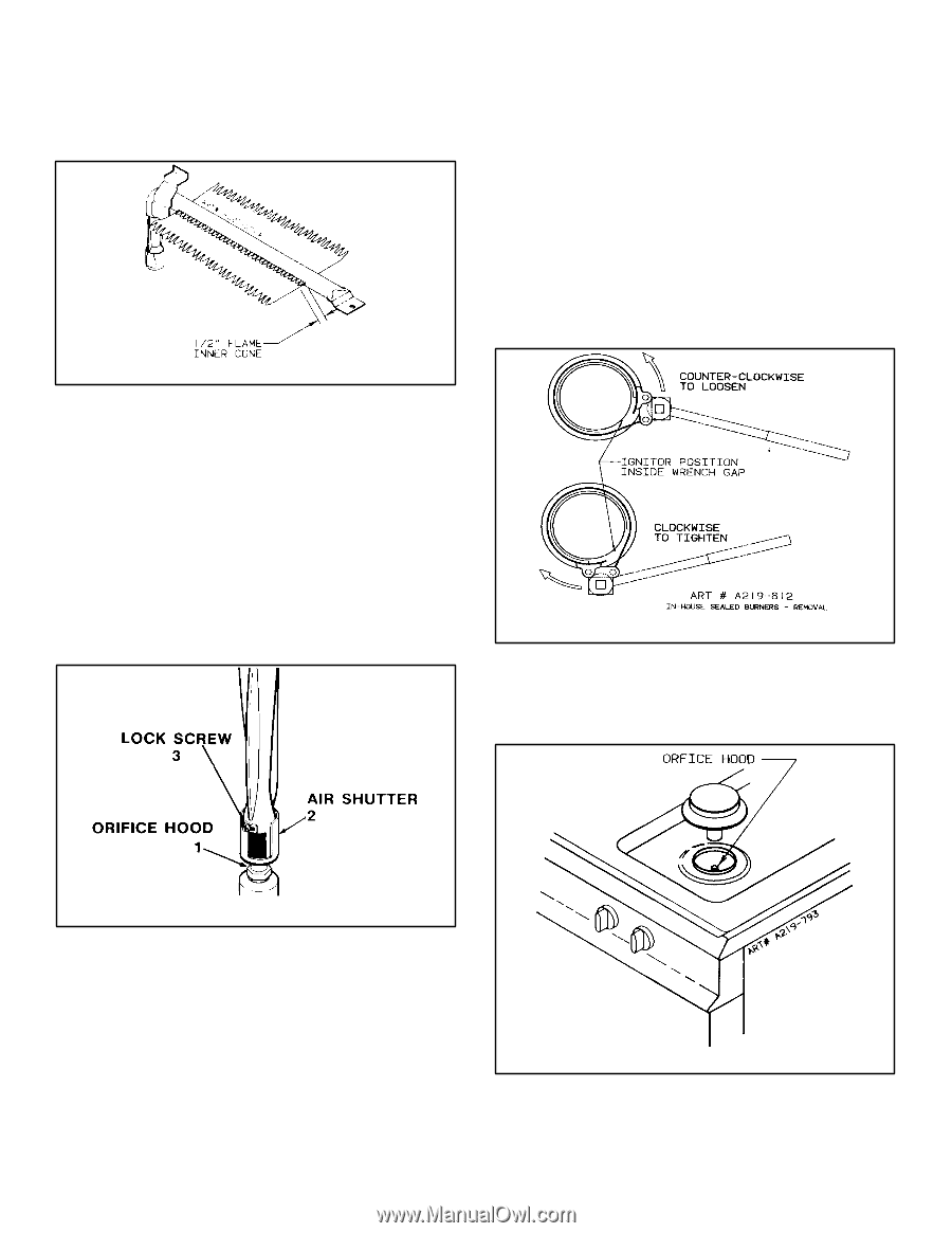
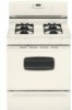
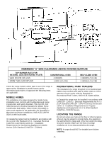
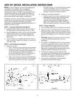
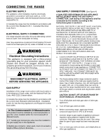
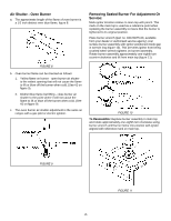
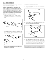
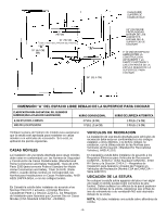
Air Shutter - Oven Burner a. The approximate length of the flame of oven burner is a 1/2 inch distinct inner blue flame, figure 8. Removing Sealed Burner For Adjustment Or Service: Mark ignitor location relative to main top with pencil. This mark on the main top is used as a reference point when replacing the burner assembly to insure that the burner is tightened to its original position. Place burner wrench (part no. 8312D075-60, available from your dealer or authorized service agency) over surface burner assembly with ignitor positioned inside gap in wrench ring (figure 10). This prevents ignitor from being crushed when wrench tightens on burner assembly. Rotate burner assembly approximately one-eighth turn counter-clockwise and lift from main top (figure 11). FIGURE 8 b. Oven burner flame can be checked as follows: 1. Yellow flame on burner - open burner air shutter to the widest opening that will not cause the flame to lift or blow off the burner when cold. (See #2 on figure 9). 2. Distinct blue flame but lifting - close burner air shutter to the point where it will not cause the flame to lift or blow off the burner when cold. (See #2 on figure 9). c. The oven burner air shutter adjustment is the same on ranges with a gas pilot or electric ignition. FIGURE 10 To Reassemble: Replace burner assembly in main top and rotate approximately one-eighth turn clockwise using burner wrench until burner locks into position with ignitor aligned with reference mark on main top. FIGURE 9 FIGURE 11 -8-
-
 1
1 -
2
-
 3
3 -
 4
4 -
 5
5 -
 6
6 -
 7
7 -
 8
8 -
 9
9 -
 10
10 -
 11
11 -
 12
12 -
 13
13 -
14
-
15
-
16
-
17
-
18
-
19
-
20
-
21
-
22
-
23
-
24
-
25
-
26
-
27
-
28
-
29
-
30
 |
 |