Metabo LF 724 S Operating Instructions - Page 13
Operation
 |
View all Metabo LF 724 S manuals
Add to My Manuals
Save this manual to your list of manuals |
Page 13 highlights
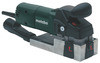
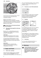
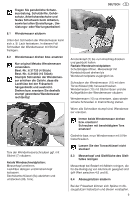
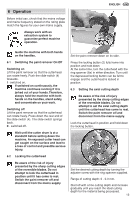
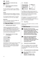
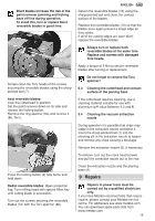
6 Operation Before initial use, check that the mains voltage and mains frequency stated on the rating plate match the figures for your own mains supply. Always work with an extraction system to guarantee perfect machine operation. ENGLISH Guide the machine with both hands on the handles. Set the paint remover down on its side. 6.1 Switching the paint remover On/Off Switching on Lift the paint remover so that the cutterhead can rotate freely. Push the slide-switch (4) forwards. I - switched on. If switched on continuously, the machine continues running if it is jerked out of your hands. Therefore, always hold the machine with both hands on the handles, stand safely, and concentrate on your work. Switching off Lift the paint remover so that the cutterhead can rotate freely. Press down the rear end of the slide-switch (4). The slide-switch springs back. 0 - switched off. Press the locking button (2) fully home into position and hold down. At the same time, turn the cutterhead with the ring spanner (8a) in either direction. Turn until the depressed locking button can be felt to engage and the cutterhead is locked in position. 6.3 Setting the axial cutting depth Be aware of the risk of injury presented by the sharp cutting edges of the reversible blades. Do not attempt to set the axial cutting depth until the cutterhead has come to rest. Switch the paint remover off and disconnect from the mains supply. Lock the cutterhead in position and hold down the locking button. Wait until the cutter drum is at a standstill before setting down the machine. An exposed cutter head can get caught on the surface and lead to a loss of control and possible serious injury. 6.2 Locking the cutterhead Be aware of the risk of injury presented by the sharp cutting edges of the reversible blades. Do not attempt to lock the cutterhead in position until it has come to rest. Switch the paint remover off and disconnect from the mains supply. Set the desired cutting depth by turning the adjuster screw with the ring spanner supplied. Range of cutting depth: 0 - 0.3 mm. Start off with a fine cutting depth and increase gradually until you reach the ideal cutting depth for the material being processed. 13
-
 1
1 -
2
-
3
-
4
-
5
-
6
-
7
-
 8
8 -
 9
9 -
 10
10 -
 11
11 -
 12
12 -
 13
13 -
 14
14 -
 15
15 -
 16
16 -
 17
17 -
 18
18 -
19
-
20
-
21
-
22
-
23
-
24
-
25
-
26
-
27
-
28
-
29
-
30
-
31
-
32
-
33
-
34
-
35
-
36
-
37
-
38
-
39
-
40
-
41
-
42
-
43
-
44
-
45
-
46
-
47
-
48
-
49
-
50
-
51
-
52
-
53
-
54
-
55
-
56
-
57
-
58
-
59
-
60
-
61
-
62
-
63
-
64
-
65
-
66
-
67
-
68
-
69
-
70
-
71
-
72
-
73
-
74
-
75
-
76
-
77
-
78
-
79
-
80
-
81
-
82
-
83
-
84
-
85
-
86
-
87
-
88
-
89
-
90
-
91
-
92
-
93
-
94
-
95
-
96
-
97
-
98
-
99
-
100
-
101
-
102
-
103
-
104
 |
 |