Netgear FS509 Installation Guide - Page 18
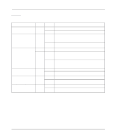
Table 2-1, Appendix B, Connector Pin Assignments, Cabling Guidelines.
 |
View all Netgear FS509 manuals
Add to My Manuals
Save this manual to your list of manuals |
Page 18 highlights
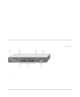
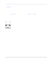
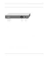
Installation Guide for the Model FS509 Fast Ethernet Switch As Figure 2-1 shows, the Model FS509 switch is equipped with eight autosensing 10/100 Mbps Fast Ethernet UTP ports. The network access speed for the 10/100 Mbps ports is automatically sensed and displayed on the front panel by the 10 Mbps or 100 Mbps Link LEDs. The 10/100 Mbps ports support only unshielded twisted pair (UTP) cable using an 8-pin RJ-45 plug. Each of the 10/100 Mbps ports uses vista RJ-45 connectors that have built-in LEDs, as illustrated in Figure 2-2. The LEDs, as described in Table 2-1 on page 2-5, indicate that the connection to the port is valid and that the port is operating at either 10 or 100 Mbps. For further information about the vista RJ-45 connector and the RJ-45 plug, refer to Appendix B, "Connector Pin Assignments," and Appendix C, "Cabling Guidelines." 1 2 735EA Key: 1 = 100M link LED 2 = 10M link LED Figure 2-2. The Vista RJ-45 Connector with Built-In LEDs 2-2 Physical Description
-
 1
1 -
2
-
3
-
4
-
5
-
6
-
7
-
8
-
9
-
10
-
11
-
12
-
 13
13 -
 14
14 -
 15
15 -
 16
16 -
 17
17 -
 18
18 -
 19
19 -
 20
20 -
 21
21 -
 22
22 -
 23
23 -
24
-
25
-
26
-
27
-
28
-
29
-
30
-
31
-
32
-
33
-
34
-
35
-
36
-
37
-
38
-
39
-
40
-
41
-
42
-
43
-
44
-
45
-
46
-
47
-
48
-
49
-
50
 |
 |
