Netgear FS509 Installation Guide - Page 32
Connecting Devices to the Switch, FDX/AUTO Duplex 10/100 Toggle Switches, Installation
 |
View all Netgear FS509 manuals
Add to My Manuals
Save this manual to your list of manuals |
Page 32 highlights
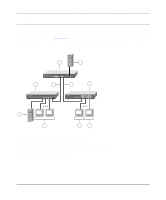
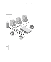
Installation Guide for the Model FS509 Fast Ethernet Switch 5. Insert two pan-head screws with nylon washers through each bracket and into the rack. 6. Using a #2 Phillips screwdriver, tighten the screws to secure the switch to the rack. For proper ventilation, make sure that the switch has at least 2 inches of space on each side and 5 inches of space at the back. It is very important that the fans located in the rear panel are not blocked. Caution: Restricted airflow could cause overheating of the components. To connect additional switches or other devices, refer to "Connecting Devices to the Switch." Connecting Devices to the Switch To connect devices to the switch: 1. Connect the devices to the 10/100 Mbps ports on the switch, using Category 5 UTP cable and an RJ-45 plug. Note: Ethernet specifications limit the cable length between your PC or server and the switch to 328 feet (100 meters) in length. 2. Connect one end of the fiber cable to the Gigabit uplink port and the other end to the linking server or network device. 3. Check the FDX / AUTO toggle switches on the rear panel for the selected duplex mode (the default setting is AUTO) for ports 1 through 8. For a typical configuration, set the toggle switches to AUTO. For more information, refer to "FDX/AUTO Duplex 10/100 Toggle Switches" in Chapter 4, "Installation." 4. Check the ON/OFF link negotiation toggle switch on the rear panel for port 9 (the 1000 Mbps gigabit Ethernet port). 4-4 Installation
-
 1
1 -
2
-
3
-
4
-
5
-
6
-
7
-
8
-
9
-
10
-
11
-
12
-
13
-
14
-
15
-
16
-
17
-
18
-
19
-
20
-
21
-
22
-
23
-
24
-
25
-
26
-
 27
27 -
 28
28 -
 29
29 -
 30
30 -
 31
31 -
 32
32 -
 33
33 -
 34
34 -
 35
35 -
 36
36 -
 37
37 -
38
-
39
-
40
-
41
-
42
-
43
-
44
-
45
-
46
-
47
-
48
-
49
-
50
 |
 |
