Netgear FS509 Installation Guide - Page 45
C-1, illustrates straight-through twisted pair cable.
 |
View all Netgear FS509 manuals
Add to My Manuals
Save this manual to your list of manuals |
Page 45 highlights
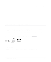
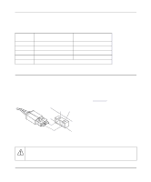
Installation Guide for the Model FS509 Fast Ethernet Switch Figure C-1 illustrates straight-through twisted pair cable. 1 Tx 2 A 3 Rx 6 1 Rx 2 B 3 Tx 6 Key: A = Uplink or MDI port (as on a PC) B = Normal or MDI-X port (as on a hub or switch) 1, 2, 3, 6 = Pin numbers 736EA Figure C-1. Straight-Through Twisted Pair Cable Figure C-2 illustrates crossover twisted pair cable. 1 Rx 2 B 3 Tx 6 1 Rx 2 B 3 Tx 6 737EA Key: B = Normal or MDI-X port (as on a hub or switch) 1, 2, 3, 6 = Pin numbers Figure C-2. Crossover Twisted Pair Cable Cabling Guidelines C-3
-
 1
1 -
2
-
3
-
4
-
5
-
6
-
7
-
8
-
9
-
10
-
11
-
12
-
13
-
14
-
15
-
16
-
17
-
18
-
19
-
20
-
21
-
22
-
23
-
24
-
25
-
26
-
27
-
28
-
29
-
30
-
31
-
32
-
33
-
34
-
35
-
36
-
37
-
38
-
39
-
 40
40 -
 41
41 -
 42
42 -
 43
43 -
 44
44 -
 45
45 -
 46
46 -
 47
47 -
 48
48 -
 49
49 -
 50
50
 |
 |

Installation Guide for the Model FS509 Fast Ethernet Switch
Cabling Guidelines
C-3
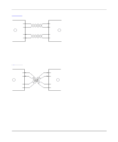
Figure C-1
illustrates straight-through twisted pair cable.
Key:
A = Uplink or MDI port (as on a PC)
B = Normal or MDI-X port (as on a hub or switch)
1, 2, 3, 6 = Pin numbers
Figure C-1.
Straight-Through Twisted Pair Cable
Figure C-2
illustrates crossover twisted pair cable.
Key:
B = Normal or MDI-X port (as on a hub or switch)
1, 2, 3, 6 = Pin numbers
Figure C-2.
Crossover Twisted Pair Cable
736EA
Tx
Rx
1
2
3
6
Tx
Rx
1
2
3
6
A
B
737EA
B
B
1
2
3
6
1
2
3
6
Tx
Rx
Tx
Rx