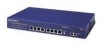
Netgear FS509 Installation Guide - Page 42
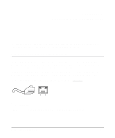
Duplex SC Plug and Duplex SC Connector, B-2
 |
View all Netgear FS509 manuals
Add to My Manuals
Save this manual to your list of manuals |
Page 42 highlights
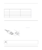
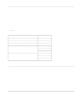
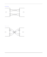
Installation Guide for the Model FS509 Fast Ethernet Switch Table B-1 lists the pin assignments for the RJ-45 plug and the vista RJ-45 connector. Table B-1. Pin 1 2 3 6 4, 5, 7, 8 RJ-45 Plug and Vista RJ-45 Connector Pin Assignments Normal Assignment on Ports 1 to 8 Uplink Assignment on Port 8 Input Receive Data + Output Transmit Data + Input Receive Data - Output Transmit Data - Output Transmit Data + Output Transmit Data - Input Receive Data + Input Receive Data - Internal termination, not used for data transmission Duplex SC Plug and Duplex SC Connector The duplex SC connector connects stations, hubs, and switches that support the 1000BASE-SX fiber interface. Each fiber link needs a clearly defined, external crossover. In other words, the transmit port of one interface must be wired to the receive port of the opposite interface and vice versa. Fiber cables must be connected in this manner to transmit and receive data. The duplex SC connector and duplex SC plug are illustrated in Figure B-2. TX RX Figure B-2. 8895FA Duplex SC Connector and Duplex SC Plug Connection Warning: Fiber optic equipment can emit laser or infrared light that might injure your eyes. Never look into an optical fiber or connector port. Always assume that fiber optic cables are connected to a light source. B-2 Connector Pin Assignments
-
 1
1 -
2
-
3
-
4
-
5
-
6
-
7
-
8
-
9
-
10
-
11
-
12
-
13
-
14
-
15
-
16
-
17
-
18
-
19
-
20
-
21
-
22
-
23
-
24
-
25
-
26
-
27
-
28
-
29
-
30
-
31
-
32
-
33
-
34
-
35
-
36
-
 37
37 -
 38
38 -
 39
39 -
 40
40 -
 41
41 -
 42
42 -
 43
43 -
 44
44 -
 45
45 -
 46
46 -
 47
47 -
48
-
49
-
50
 |
 |
