Netgear FS518T FS518 Installation Guide - Page 17
Physical Description, Front Panel
 |
UPC - 606449020366
View all Netgear FS518T manuals
Add to My Manuals
Save this manual to your list of manuals |
Page 17 highlights
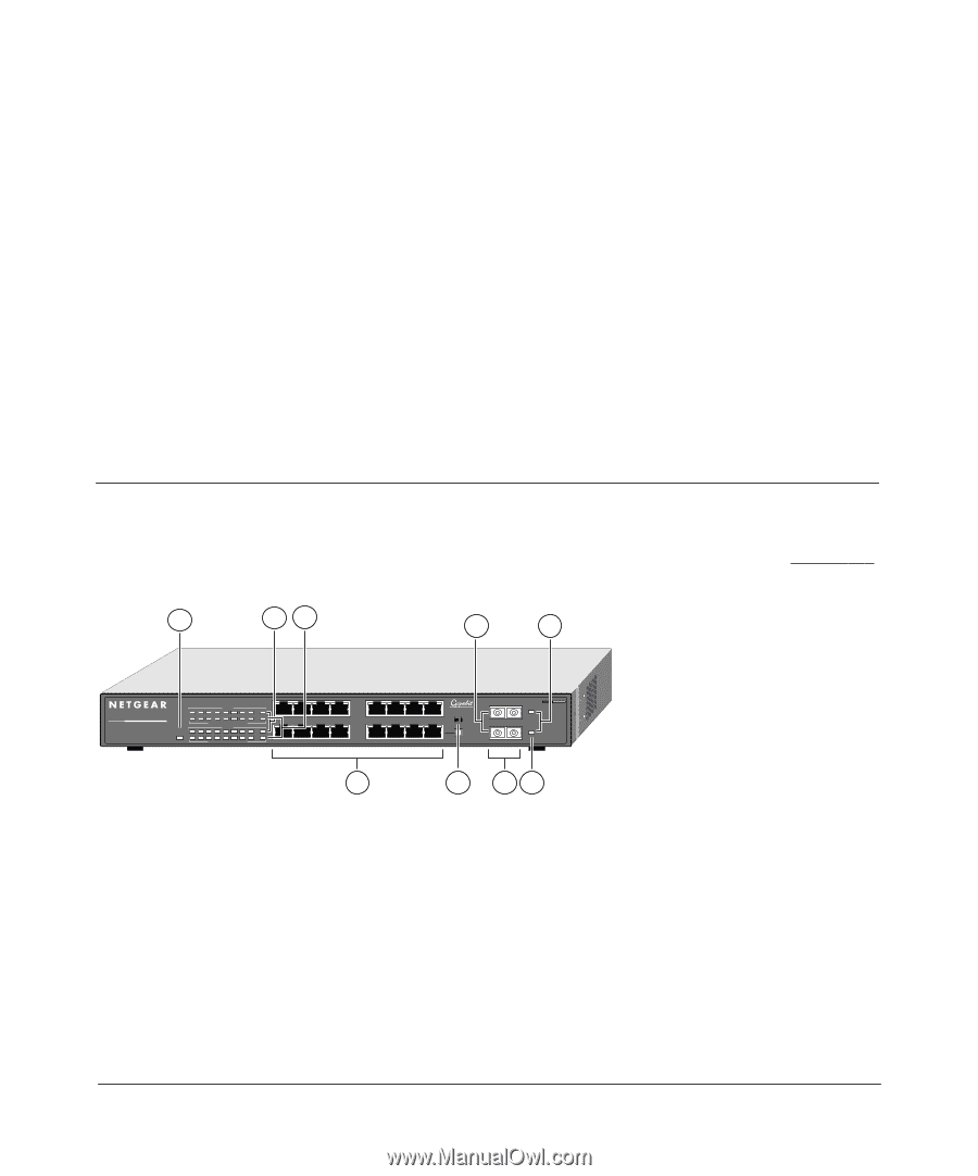
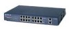
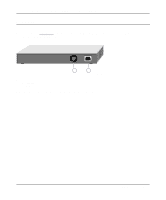
Chapter 2 Physical Description This chapter describes the hardware features of the NETGEAR Model FS518 Fast Ethernet Switch. Front Panel For easier management and control of the Model FS518 switch, familiarize yourself with the ports, LEDs, and Normal/Uplink push button on the front panel of the switch, as illustrated in Figure 2-1. 1 23 6 7 18PORT 10/100Mbps Fast Ethernet Switch Power Rx/Tx 1 234 5 678 Green = FDX, Yellow = COL Rx/Tx 9 10 11 12 13 14 15 16 Green = FDX, Yellow = COL 17 1 100M 10M 18 9 45 12 13 Ethernet 8 On = Link Normal/Uplink 16 Tx Rx Tx Rx MODEL FS518 1000M Link 1000M Link 4 5 67 9307FA Key: 1 = Power LED 2 = RX/TX LEDs 3 = FDX/COL LEDs 4 = 10/100 Mbps UTP ports with 10M or 100M Link LEDs on each port 5 = Normal/Uplink push button for port 16 6 = Gigabit Ethernet (1000BASE-SX) SC fiber ports 7 = Link LEDs for the Gigabit Ethernet ports Figure 2-1. Front Panel of the Model FS518 Switch Physical Description 2-1
-
 1
1 -
2
-
3
-
4
-
5
-
6
-
7
-
8
-
9
-
10
-
11
-
 12
12 -
 13
13 -
 14
14 -
 15
15 -
 16
16 -
 17
17 -
 18
18 -
 19
19 -
 20
20 -
 21
21 -
 22
22 -
23
-
24
-
25
-
26
-
27
-
28
-
29
-
30
-
31
-
32
-
33
-
34
-
35
-
36
-
37
-
38
-
39
-
40
-
41
-
42
-
43
-
44
-
45
-
46
-
47
-
48
 |
 |