Netgear FS518T FS518 Installation Guide - Page 7
s, Category 5 UTP Patch Cable with Male RJ-45 Plug at Each End
 |
UPC - 606449020366
View all Netgear FS518T manuals
Add to My Manuals
Save this manual to your list of manuals |
Page 7 highlights
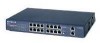
Figures Figure 2-1. Figure 2-2. Figure 2-3. Figure 2-4. Front Panel of the Model FS518 Switch 2-1 Vista RJ-45 Connector with Built-In LEDs 2-2 1000BASE-SX Fiber Connection 2-3 Rear Panel of the Model FS518 Switch 2-6 Figure 3-1. Model FS518 Switch Used as a Desktop Switch 3-2 Figure 3-2. Model FS518 Switch Used as a Segment Switch 3-3 Figure 4-1. Figure 4-2. Figure 4-3. Attaching Mounting Brackets to the Model FS518 Switch 4-3 Tx/Rx Connection Between Switches 4-5 Connecting to the Model FS518 Fast Ethernet Switch 4-6 Figure B-1. RJ-45 Plug and Vista RJ-45 Connector with Built-In LEDs B-1 Figure B-2. Duplex SC Connector and Duplex SC Plug Connection B-2 Figure C-1. Figure C-2. Figure C-3. Straight-Through Twisted Pair Cable C-3 Crossover Twisted Pair Cable C-3 Category 5 UTP Patch Cable with Male RJ-45 Plug at Each End .......... C-4 Figures vii
-
 1
1 -
 2
2 -
 3
3 -
 4
4 -
 5
5 -
 6
6 -
 7
7 -
 8
8 -
 9
9 -
 10
10 -
 11
11 -
 12
12 -
13
-
14
-
15
-
16
-
17
-
18
-
19
-
20
-
21
-
22
-
23
-
24
-
25
-
26
-
27
-
28
-
29
-
30
-
31
-
32
-
33
-
34
-
35
-
36
-
37
-
38
-
39
-
40
-
41
-
42
-
43
-
44
-
45
-
46
-
47
-
48
 |
 |
