Netgear FS518T FS518 Installation Guide - Page 21
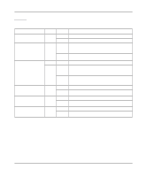
Tdescribes each LED on the front panel of the Model FS518 switch.
 |
UPC - 606449020366
View all Netgear FS518T manuals
Add to My Manuals
Save this manual to your list of manuals |
Page 21 highlights
Installation Guide for the Model FS518 Fast Ethernet Switch Table 2-1 describes each LED on the front panel of the Model FS518 switch. Table 2-1. LED Descriptions Label Power RX/TX FDX/COL Color Green Green Green Yellow 100M Link (located at the Green top left corner of each 10/100 Mbps UTP port) 10M Link (located at the top right corner of each 10/100 Mbps UTP port) Green 1000 Mbps Link (located Green to the right of the fiber connector) Activity On Off Blinking Off On On Off On Off Description Power is supplied to the switch. Power is disconnected. Packet transmission or reception is occurring on the port. The blinking action corresponds to the number of packets that are transmitted or received. No packet transmission or reception is occurring on the port. A full-duplex link is established on the port. A half-duplex link is established on the port, and the port is experiencing collisions. (Note that occasional collisions are normal.) No full-duplex link is established, or no collisions are occurring on the port when operating in half-duplex mode. A valid 100 Mbps link is established on the port. No 100 Mbps link is established on the port. On A valid 10 Mbps link is established on the port. Off No 10 Mbps link is established on the port. On A valid 1000 Mbps link is established on the port. Off No 1000 Mbps link is established on the port. Physical Description 2-5
-
 1
1 -
2
-
3
-
4
-
5
-
6
-
7
-
8
-
9
-
10
-
11
-
12
-
13
-
14
-
15
-
 16
16 -
 17
17 -
 18
18 -
 19
19 -
 20
20 -
 21
21 -
 22
22 -
 23
23 -
 24
24 -
 25
25 -
 26
26 -
27
-
28
-
29
-
30
-
31
-
32
-
33
-
34
-
35
-
36
-
37
-
38
-
39
-
40
-
41
-
42
-
43
-
44
-
45
-
46
-
47
-
48
 |
 |
