Netgear FS518T FS518 Installation Guide - Page 31
Connecting Devices to the Switch, when connecting the Model FS518 switch.
 |
UPC - 606449020366
View all Netgear FS518T manuals
Add to My Manuals
Save this manual to your list of manuals |
Page 31 highlights
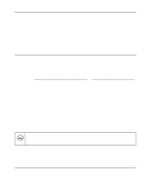
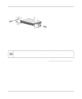
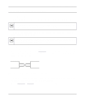
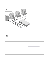
Installation Guide for the Model FS518 Fast Ethernet Switch Connecting Devices to the Switch To connect devices to the switch: 1. Connect the devices to the 10/100 Mbps ports on the switch, using Category 5 UTP cable. Note: Ethernet specifications limit the cable length between your PC or server and the switch to 328 feet (100 meters) in length. 2. Connect one end of the fiber cable to the Gigabit uplink port and the other end to the linking server or network device. Note: Gigabit Ethernet fiber cable lengths are 260 m with 62.5 µm multimode fiber and 525 m with 50 µm multimode fiber. Ensure that the Tx (transmit data) Gigabit fiber connector of the Model FS518 switch is attached to the Rx (receive data) Gigabit fiber connector of the remote partner using one of the pairs of the fiber cable, as illustrated in Figure 4-2. Be sure that the Rx Gigabit fiber connector of the switch is attached to the Tx Gigabit fiber connector of the remote partner using the other pair from the same fiber cable. Model FS518 switch Tx Rx Remote Partner Tx Rx 9332EA Figure 4-2. Tx/Rx Connection Between Switches 3. Connect one end of the AC power cord to the power outlet on the rear panel of the switch and the other end of the AC power cord to the wall outlet. Refer to Figure 4-3 on page 4-6 when connecting the Model FS518 switch. Installation 4-5
-
 1
1 -
2
-
3
-
4
-
5
-
6
-
7
-
8
-
9
-
10
-
11
-
12
-
13
-
14
-
15
-
16
-
17
-
18
-
19
-
20
-
21
-
22
-
23
-
24
-
25
-
 26
26 -
 27
27 -
 28
28 -
 29
29 -
 30
30 -
 31
31 -
 32
32 -
 33
33 -
 34
34 -
 35
35 -
 36
36 -
37
-
38
-
39
-
40
-
41
-
42
-
43
-
44
-
45
-
46
-
47
-
48
 |
 |