Netgear GS724TPv2 Hardware Installation Guide - Page 11
Back Panel, LEDs, Table 2. Front panel LEDs, Hardware Overview
 |
View all Netgear GS724TPv2 manuals
Add to My Manuals
Save this manual to your list of manuals |
Page 11 highlights
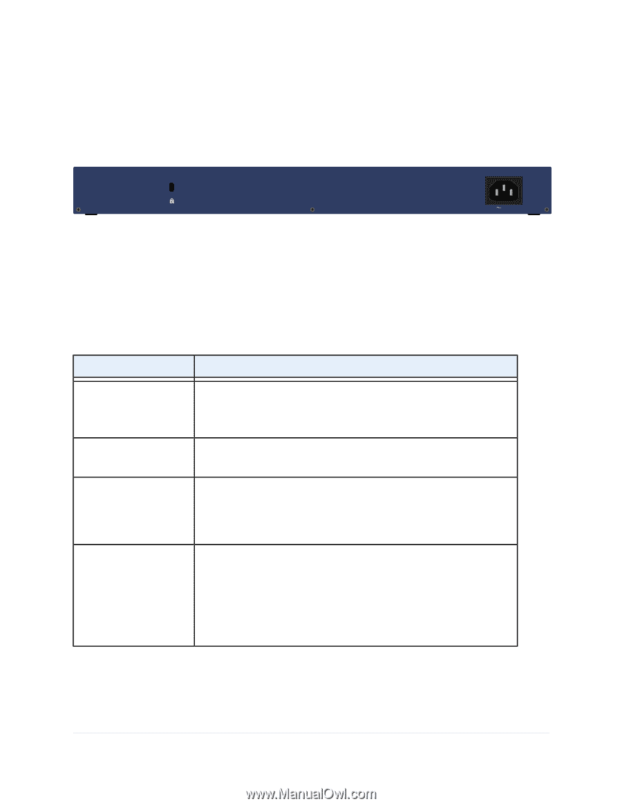
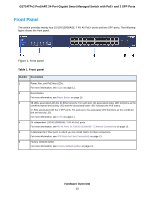
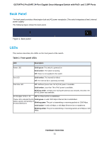
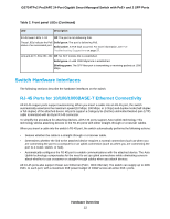
GS724TPv2 ProSAFE 24-Port Gigabit Smart Managed Switch with PoE+ and 2 SFP Ports Back Panel The back panel provides a Kensington lock and AC power receptacle. (The switch integrates a fixed, internal power supply.) The following figure shows the back panel. Figure 2. Back panel LEDs This section describes the LEDs on the front panel of the switch. Table 2. Front panel LEDs LED Description Power LED Solid green. The switch is powered on. Solid amber. The switch is booting. Off. Power is not supplied to the switch. Fan LED Solid amber. The internal fan failed. Off. The internal fan is operating normally. PoE Max LED Off. Sufficient (more than 7W of) PoE power is available. Solid amber. Less than 7W of PoE power is available. Blinking amber. At least once during the previous two minutes, less than 7W of PoE power was available. RJ-45 upper LEDs 1-24 Off. No Ethernet link is established. These LEDs indicate the link Solid green. A valid 1000 Mbps Ethernet link is established. status, speed, and activity of an associated port. Blinking green. The port is transmitting or receiving packets at 1000 Mbps. Solid amber. A valid 10 Mbps or 100 Mbps Ethernet link is established. Blinking amber. The port is transmitting or receiving packets at 10 Mbps or 100 Mbps. Hardware Overview 11
-
 1
1 -
2
-
3
-
4
-
5
-
 6
6 -
 7
7 -
 8
8 -
 9
9 -
 10
10 -
 11
11 -
 12
12 -
 13
13 -
 14
14 -
 15
15 -
 16
16 -
17
-
18
-
19
-
20
-
21
-
22
-
23
-
24
-
25
-
26
-
27
 |
 |