Netgear GS724TPv2 Hardware Installation Guide - Page 26
Troubleshooting Chart
 |
View all Netgear GS724TPv2 manuals
Add to My Manuals
Save this manual to your list of manuals |
Page 26 highlights
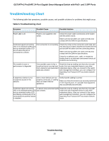
GS724TPv2 ProSAFE 24-Port Gigabit Smart Managed Switch with PoE+ and 2 SFP Ports Troubleshooting Chart The following table lists symptoms, possible causes, and possible solutions for problems that might occur. Table 6. Troubleshooting chart Symptom Possible Cause Possible Solution Power LED is off. Power is not supplied to the switch. Check the power cable connections at the switch and the power source. Make sure that all cables are used correctly and comply with the Ethernet specifications. Combined speed and activity Port connection is not working. Check the crimp on the connectors and make sure LED or an individual speed LED that the plug is properly inserted and locked into the and an individual activity LED port at both the switch and the connecting device. are off when the port is connected to a device. Make sure that all cables are used correctly and comply with the Ethernet specifications. Check for a defective port, cable, or module by testing them in an alternate environment where all products are functioning. File transfer is slow or performance is degraded. One possible cause is that a broadcast storm occurred and that a network loop (redundant path) was created. Break the loop by making sure that only one path exists from any networked device to any other networked device. After you connect to the switch web management interface, you can configure the Spanning Tree Protocol (STP) to prevent network loops. A segment or device is not recognized as part of the network. One or more devices are not properly connected, or cabling does not meet Ethernet guidelines. Verify that the cabling is correct. Make sure that all connectors are securely positioned in the required ports. It is possible that equipment was accidentally disconnected. Combined speed and activity A network loop (redundant path) Break the loop by making sure that only one path LED or an individual speed LED was created. exists from any networked device to any other and an individual activity LED networked device. After you connect to the switch are blinking continuously on all web management interface, you can configure the connected ports and the network Spanning Tree Protocol (STP) to prevent network is disabled. loops. Troubleshooting 26
-
 1
1 -
2
-
3
-
4
-
5
-
6
-
7
-
8
-
9
-
10
-
11
-
12
-
13
-
14
-
15
-
16
-
17
-
18
-
19
-
20
-
 21
21 -
 22
22 -
 23
23 -
 24
24 -
 25
25 -
 26
26 -
 27
27
 |
 |