Netgear GSM7212P GSM5212P/GSM7212P/GSM7212F/GSM7224P Setup Manual - Page 7
Netgear GSM7212P Manual
 |
View all Netgear GSM7212P manuals
Add to My Manuals
Save this manual to your list of manuals |
Page 7 highlights
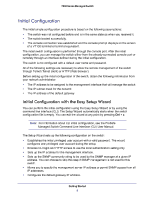
7000 Series Managed Switch 3. Configure the COM port as follows: a. Set the data rate to 9600 baud. b. Set the data format to 8 data bits, 1 stop bit, and no parity. c. Set the flow control to none. d. Select the correct mode under Properties. e. Select Terminal keys. The Log-in User prompt displays when the terminal interface initializes. 4. Enter an approved user name and password. The default is admin for the user name, and the password is blank. The switch is installed and loaded with the default configuration. 5. Reduce network traffic by turning off the Network Configuration Protocol. Enter the following command: configure network protocol none 6. Set the IP address, subnet mask, and gateway address by issuing the following command: config network parms ipaddress netmask gateway IP Address: Unique IP address for the switch. Each IP parameter is made up of four decimal numbers, ranging from 0 to 255. The default IP address is 169.254.100.100. Subnet: Subnet mask for the LAN. The default value is 255.255.255.0. Gateway: Subnet mask for the LAN. The default value is 255.255.255.0. 7. To enable these changes to be retained during a reset of the switch, press Ctrl + z to return to the main prompt, type save at the main menu prompt, and type y to confirm the changes. 8. To view the changes and verify in-band information, issue the command: show network. 9. The switch is configured for in-band connectivity and ready for Web-based management. Configuring the Switch for Out-of-Band Connectivity To monitor and configure the switch using out-of-band connectivity, use the console port to connect the switch to a terminal desktop system running terminal emulation software. The console port connector is a male DB-9 connector, implemented as a data terminal equipment (DTE) connector. The following hardware is required to use the console port: • • VT100-compatible terminal, or a desktop, or a portable system with a serial port running VT100 terminal emulation software. An RS-232 crossover cable with a female DB-9 connector for the console port and the appropriate connector for the terminal. Getting Started 7
-
 1
1 -
 2
2 -
 3
3 -
 4
4 -
 5
5 -
 6
6 -
 7
7 -
 8
8 -
 9
9 -
 10
10 -
 11
11 -
 12
12 -
13
-
14
-
15
-
16
-
17
-
18
-
19
-
20
-
21
-
22
-
23
-
24
-
25
-
26
-
27
-
28
-
29
-
30
-
31
-
32
-
33
-
34
-
35
-
36
 |
 |
