Netgear GSM7328S-200NAS User Guide - Page 10
Physical Description
 |
View all Netgear GSM7328S-200NAS manuals
Add to My Manuals
Save this manual to your list of manuals |
Page 10 highlights
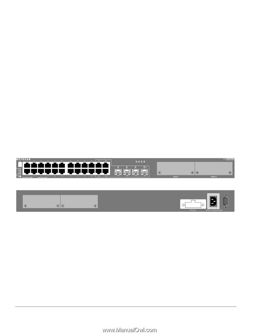
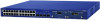
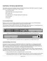
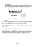
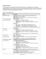
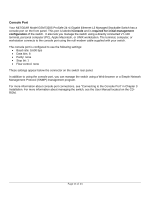
CHAPTER 2: PHYSICAL DESCRIPTION This chapter describes the hardware features of the NETGEAR Model GSM7328S ProSafe 24+4 Gigabit Ethernet L3 Managed Stackable Switch. Topics include: Front and back panels 10/100/1000 Mbps auto-sensing RJ-45 ports SFP module ports 10 Gigabit Ethernet / 24 Gigabit Stacking I/O module bays LED descriptions Console port Front and Back Panels Figures 2-1 and 2-2 show the key components on the front and back panels of the NETGEAR Model GSM7328S ProSafe 24+4 Gigabit Ethernet L3 Managed Stackable Switch The front panel contains LEDs, RJ-45 jacks, SFP module bays, and a console port. The back panel has a standard AC power receptacle for accommodating the supplied power cord. Figure 2-1. Front Panel of the GSM7328S ProSafe 24+4 Gigabit Ethernet L3 Managed Stackable Switch Figure 2-2. Back Panel of the GSM7328S ProSafe 24+4 Gigabit Ethernet L3 Managed Stackable Switch 10/100/1000 Mbps RJ-45 Ports As Figures 2-1 and 2-3 shows, the GSM7328S ProSafe 24+4 Gigabit Ethernet L3 Managed Stackable Switch has 24 10/100/1000 Mbps RJ-45 ports. These ports are auto-sensing 10/100/1000 Mbps ports: When you insert a cable into an RJ-45 port, the switch automatically ascertains the maximum speed (10, 100, or 1000 Mbps) and duplex mode (half- or full-duplex) of the attached device. To simplify the procedure for attaching devices, all RJ-45 ports support Auto Uplink. This technology lets you attach devices to the RJ-45 ports using either straight-through or crossover cables. When you insert a cable into the switch's RJ-45 port, the switch automatically: • Senses whether the cable is a straight-through or crossover cable. • Determines whether the link to the attached device requires a "normal" connection (such as when connecting the port to a PC) or an "uplink" connection (such as when connecting the port to a Page 10 of 24
-
 1
1 -
2
-
3
-
4
-
 5
5 -
 6
6 -
 7
7 -
 8
8 -
 9
9 -
 10
10 -
 11
11 -
 12
12 -
 13
13 -
 14
14 -
 15
15 -
16
-
17
-
18
-
19
-
20
-
21
-
22
-
23
-
24
-
25
-
26
 |
 |