Netgear GSM7328S-200NAS User Guide - Page 20
Step 10: Connecting to RPS System
 |
View all Netgear GSM7328S-200NAS manuals
Add to My Manuals
Save this manual to your list of manuals |
Page 20 highlights
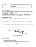
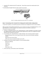
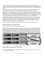
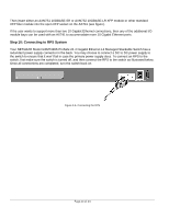
Then insert either an AXM751 10GBASE-SR or AXM752 10GBASE-LR XFP module or other standard XFP fiber module into the open XFP socket on the AX741 (see figure). If the user wants to support more than two 10 Gigabit Ethernet connections, then any of the additional I/O module bays can be used with an AX741 to accommodate more 10 Gigabit Ethernet ports. Step 10: Connecting to RPS System Your NETGEAR Model GSM7328S ProSafe 24+4 Gigabit Ethernet L3 Managed Stackable Switch has a redundant power supply connector in the back. You may choose to connect a DC to DC power supply to the switch to ensure that it won't fail in case the primary power supply does. To connect an RPS to the switch, first make sure the switch is turned off, and then connect the RPS to the switch as illustrated below. Once all connections are completed, turn the switch back on. Figure 3-6. Connecting the RPS Page 20 of 24
-
 1
1 -
2
-
3
-
4
-
5
-
6
-
7
-
8
-
9
-
10
-
11
-
12
-
13
-
14
-
 15
15 -
 16
16 -
 17
17 -
 18
18 -
 19
19 -
 20
20 -
 21
21 -
 22
22 -
 23
23 -
 24
24 -
 25
25 -
26
 |
 |