Netgear GSM7328S-200NAS User Guide - Page 14
Installation
 |
View all Netgear GSM7328S-200NAS manuals
Add to My Manuals
Save this manual to your list of manuals |
Page 14 highlights
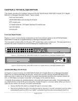
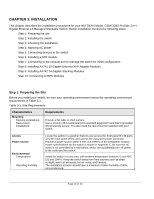
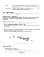
CHAPTER 3: INSTALLATION This chapter describes the installation procedures for your NETGEAR Model GSM7328S ProSafe 24+4 Gigabit Ethernet L3 Managed Stackable Switch. Switch installation involves the following steps: Step 1: Preparing the site Step 2: Installing the switch Step 3: Checking the installation Step 4: Applying AC power Step 5: Connecting devices to the switch Step 6: Installing a SFP module Step 7: Connecting to the console port to manage the switch for initial configuration Step 8: Installing AX741 10-Gigabit Ethernet XFP Adapter Modules Step 9: Installing AX742 24-Gigabit Stacking Modules Step 10: Connecting to RPS Modules Step 1: Preparing the Site Before you install your switch, be sure your operating environment meets the operating environment requirements in Table 3-1. Table 3-1. Site Requirements Characteristics Mounting Desktop installations: Rack-mount installations: Requirements Provide a flat table or shelf surface. Use a 19-inch (48.3-centimeter) EIA standard equipment rack that is grounded and physically secure. You also need the rack-mount kit supplied with your switch. Access Power source Environmental Temperature: Operating humidity: Locate the switch in a position that lets you access the front panel RJ-45 ports, view the front panel LEDs, and access the rear-panel power connector. Provide a power source within 6 feet (1.8 meters) of the installation location. Power specifications for the switch is shown in Appendix C. Be sure the AC outlet is not controlled by a wall switch, which can accidentally turn off power to the outlet and the switch. Install the switch in a dry area, with ambient temperature between 0 and 40ºC (32 and 104ºF). Keep the switch away from heat sources such as direct sunlight, warm air exhausts, hot-air vents, and heaters. The installation location should have a maximum relative humidity of 90%, non-condensing. Page 14 of 24
-
 1
1 -
2
-
3
-
4
-
5
-
6
-
7
-
8
-
 9
9 -
 10
10 -
 11
11 -
 12
12 -
 13
13 -
 14
14 -
 15
15 -
 16
16 -
 17
17 -
 18
18 -
 19
19 -
20
-
21
-
22
-
23
-
24
-
25
-
26
 |
 |