Netgear GSM7328S-200NAS User Guide - Page 19
Step 8: Connecting the stacking modules, Step 9: Setup 10 Gigabit Ethernet Connections - gsm7352s
 |
View all Netgear GSM7328S-200NAS manuals
Add to My Manuals
Save this manual to your list of manuals |
Page 19 highlights
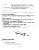
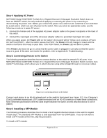
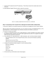
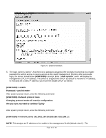
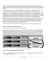
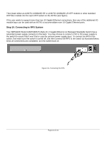
management VLAN is a special VLAN that is isolated from other normal routable VLANs for security reasons. If you wish to assign an IP address to the switch in a normal VLAN, please follow the instructions found in Chapter 6: Quick Startup of the User Manual for the Netgear 7300 Series Layer 3 Managed Switch Software. The example above uses "192.168.1.100" as IP address, and "192.168.1.1" as gateway IP address. The gateway address is optional. You should provide your own IP address in the above command. If you want to use your web browser, or telnet session to manage your switch, note the IP address on the Sysinfo page. To use your web browser, simply type the IP address in the URL address bar and hit enter. If you want to use an SNMP management application, you will need to note the IP address and to configure the SNMP settings in your switch so that it will respond to SNMP requests. This configuration can be done through either the console or web browser GUI. See User Guide on how to enable SNMP access. Note: The switch IP address is by default using DHCP mode to assign its address. If you leave the switch IP mode in the default DHCP mode, the IP address of your switch could change, and you would have to reconnect to the switch via the console port to discover the new IP address. Change the IP mode to Manual for a more reliable connection. If you need help changing the IP mode, please refer the User Manual on the Resource CD for Layer 3 Managed Switches. To learn more about the managed features on your switch, refer to the manual on the Resource CD. Step 8: Connecting the stacking modules Perform this step only if you are setting up a stack of switches. GSM7328S can be setup as part of a stack. To setup the stack, first plug the AX742 24 Gigabit Stacking modules into the available I/O module bays at the front or the rear of the case, then connect the provided stacking XENPAK cables to the same AX742 24 Gigabit Stacking modules on the other 2 GSM7328S or GSM7352S (upstream and downstream). The switches will automatically select a master unit. Once the master is selected its console will be accessible as normal, and other non-master units' console ports will no longer provide the normal CLI access. The following diagram illustrates how the stack can be created. Figure 3-5. Connecting the stacking modules Step 9: Setup 10 Gigabit Ethernet Connections To set up a 10 Gigabit Ethernet connection, first plug an AX741 10 Gigabit Ethernet XFP Adapter into one of the available I/O module bays. Page 19 of 24
-
 1
1 -
2
-
3
-
4
-
5
-
6
-
7
-
8
-
9
-
10
-
11
-
12
-
13
-
 14
14 -
 15
15 -
 16
16 -
 17
17 -
 18
18 -
 19
19 -
 20
20 -
 21
21 -
 22
22 -
 23
23 -
 24
24 -
25
-
26
 |
 |