Netgear GSM7328S-200NAS User Guide - Page 16
Step 4: Applying AC Power, Step 5: Connecting Devices to the Switch, Step 6: Installing a SFP Module
 |
View all Netgear GSM7328S-200NAS manuals
Add to My Manuals
Save this manual to your list of manuals |
Page 16 highlights
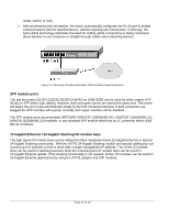
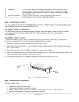
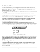
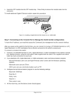
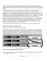
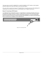
Step 4: Applying AC Power NETGEAR Model GSM7328S ProSafe 24+4 Gigabit Ethernet L3 Managed Stackable Switch does not have an ON/OFF switch; the only method of applying or removing AC power is by connecting or disconnecting the power cord. Before you connect the power cord, select an AC outlet that is not controlled by a wall switch, which can turn off power to the switch. After you select an appropriate outlet, use the following procedure to apply AC power. 1. Connect the female end of the supplied AC power adapter cable to the power receptacle on the back of the switch. 2. Connect the 3-pronged end of the AC power adapter cable to a grounded 3-pronged AC outlet. When you apply power, the Power LED on the switch's front panel will be Yellow, as it conducts a Power On Self Test (POST). After the switch passes the POST, the Power LED will change to Green and the switch is functional and ready to pass data. If the POST failed, the Power LED will blink in yellow. If the Power LED does not go on, check that the power cable is plugged in correctly and that the power source is good. If this does not resolve the problem, refer to Appendix B, Troubleshooting. Step 5: Connecting Devices to the Switch The following procedure describes how to connect devices to the switch's network RJ-45 ports. Your NETGEAR Model GSM7328S ProSafe 24+4 Gigabit Ethernet L3 Managed Stackable Switch contains Auto Uplink™ technology, which allows you to attach devices using either straight-through or crossover cables. Figure 3-2. Connecting Devices to the Switch Connect each device to an RJ-45 network port on the switch's front panel (see Figure 3-2). Use Category 5 (Cat5) unshielded twisted-pair (UTP) cable terminated with an RJ-45 connector to make these connections. Note: Ethernet specifications limit the cable length between the switch and the attached device to 100 m (328 ft). Step 6: Installing a SFP Module The following procedure describes how to install a SFP Gigabit Ethernet module in the switch's Gigabit module bays. The Standard SFP Module is sold separately from the GSM7328S. If you do not want to install a SFP module at this time, skip this procedure. To install a SFP module: Page 16 of 24
-
 1
1 -
2
-
3
-
4
-
5
-
6
-
7
-
8
-
9
-
10
-
 11
11 -
 12
12 -
 13
13 -
 14
14 -
 15
15 -
 16
16 -
 17
17 -
 18
18 -
 19
19 -
 20
20 -
 21
21 -
22
-
23
-
24
-
25
-
26
 |
 |