Panasonic AG-AC160A Operating Instructions Advanced - Page 42
Using an external microphone and audio devices, INPUT1 switch, MIC POWER +48V, INPUT1 LINE/MIC switch
 |
View all Panasonic AG-AC160A manuals
Add to My Manuals
Save this manual to your list of manuals |
Page 42 highlights
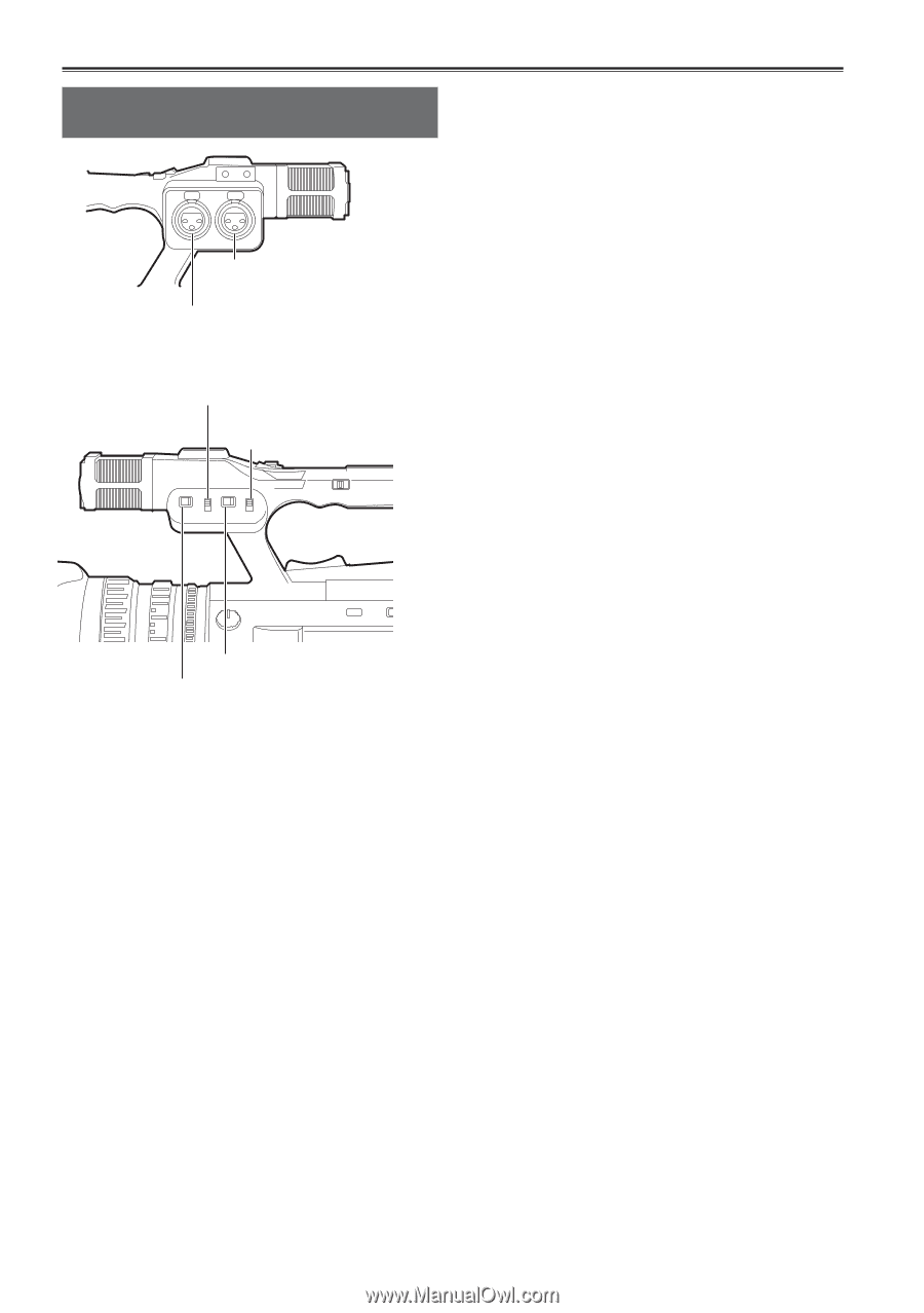
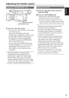
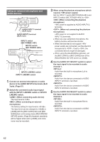
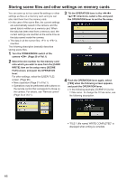
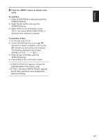
Using an external microphone and audio devices AUDIO INPUT1 terminal (XLR 3-pin) AUDIO INPUT2 terminal (XLR 3-pin) INPUT1 switch (MIC POWER +48V) INPUT2 switch (MIC POWER +48V) INPUT2 LINE/MIC switch INPUT1 LINE/MIC switch 1 Connect an external microphone or audio device to the AUDIO INPUT1/2 terminals (XLR 3-pin). (Page 67) 2 Switch the connected audio input signal with the INPUT1 LINE/MIC switch or INPUT2 LINE/MIC switch. : (When connecting audio device) The input level is 0 dBu. : (When connecting an external microphone) The factory setting for input level is -50 dBu. The input level can be changed to [-40dB] or [-60dB] with the [MIC GAIN1] item and [MIC GAIN2] item on the setup menu [RECORDING SETUP] screen. (Page 90) However, sensitivity will be higher when set to [-60dB], and more noise may be recorded. 3 When using the phantom microphone (which requires +48V power supply) Set the INPUT1 switch (MIC POWER+48V) and INPUT2 switch (MIC POWER+48V) to . : (When connecting the phantom microphone) +48V power is supplied to AUDIO INPUT1/2 terminals. : (When not connecting the phantom microphone) +48V power is not supplied to AUDIO INPUT1/2 terminals. ••When you use a phantom microphone, the battery duration will become shorter. ••When devices that do not support +48V power supply are connected, set the phantom microphone to . If set to , the connected devices might be damaged. ••When using the AG-MC200G (optional), set the [MIC GAIN1] or [MIC GAIN2] item of the [RECORDING SETUP] screen to [-50dB]. 4 Use the AUDIO CH1 SELECT switch to select the input signal to be recorded to audio channel 1. : Audio from the built-in microphone Lch is recorded. : Audio from the device connected to AUDIO INPUT1 terminal is recorded. : Audio from the device connected to AUDIO INPUT2 terminal is recorded. 5 Use the AUDIO CH2 SELECT switch to select the input signal to be recorded to audio channel 2. : Audio from the built-in microphone Rch is recorded. : Audio from the device connected to AUDIO INPUT2 terminal is recorded. 42
-
 1
1 -
2
-
3
-
4
-
5
-
6
-
7
-
8
-
9
-
10
-
11
-
12
-
13
-
14
-
15
-
16
-
17
-
18
-
19
-
20
-
21
-
22
-
23
-
24
-
25
-
26
-
27
-
28
-
29
-
30
-
31
-
32
-
33
-
34
-
35
-
36
-
 37
37 -
 38
38 -
 39
39 -
 40
40 -
 41
41 -
 42
42 -
 43
43 -
 44
44 -
 45
45 -
 46
46 -
 47
47 -
48
-
49
-
50
-
51
-
52
-
53
-
54
-
55
-
56
-
57
-
58
-
59
-
60
-
61
-
62
-
63
-
64
-
65
-
66
-
67
-
68
-
69
-
70
-
71
-
72
-
73
-
74
-
75
-
76
-
77
-
78
-
79
-
80
-
81
-
82
-
83
-
84
-
85
-
86
-
87
-
88
-
89
-
90
-
91
-
92
-
93
-
94
-
95
-
96
-
97
-
98
-
99
-
100
-
101
-
102
-
103
-
104
-
105
-
106
-
107
-
108
-
109
-
110
 |
 |