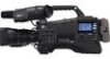
Panasonic AG-HPX600PJB Operating Instructions - Page 171
Digital audio, Video input/output, Audio input/output, Other input/output, Options
 |
View all Panasonic AG-HPX600PJB manuals
Add to My Manuals
Save this manual to your list of manuals |
Page 171 highlights
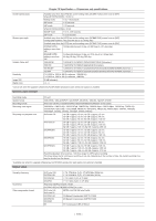
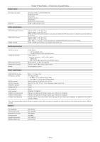
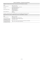
Digital audio Chapter 12 Specification - Dimensions and specifications Recording audio signal Headroom AVC‑Intra 100/AVC‑Intra 50/DVCPRO HD 48 kHz/16 bits, 4ch DVCPRO50 48 kHz/16 bits, 4ch DVCPRO/DV 48 kHz/16 bits, 2ch/4ch switch 20 dB/18 dB (switchable menu) Video input/output terminal terminal terminal HD SDI = BNC×1, 0.8 V [p-p], 75 Ω SD SDI = BNC×1, 0.8 V [p-p], 75 Ω When the HD/SD SDI input board (extra-cost option) is installed, the SDI input function is available (switched the SDI input in the menu). HD SDI = BNC×1, 0.8 V [p-p], 75 Ω SD SDI = BNC×1, 0.8 V [p-p], 75 Ω VBS = BNC×1, 1.0 V [p-p], 75 Ω (Can be switched to HD SDI/SD SDI/VBS with the SmartUI setting.) HDMI×1 (HDMI type A terminal, not compatible with VIERA Link) Audio input/output terminal terminal WIRELESS IN terminal terminal Speaker ffXLR (3-pin)×1 - +48 V supporting menu - −40 dBu/−50 dBu/−60 dBu (switchable menu) ffXLR (3-pin)×2 Input high impedance, / (switch) - LINE: 0 dBu - MIC: −50/−60 dBu (menu), MIC+48 V ON/OFF (switch) 25-pin, D-SUB, −40 dBu, 2ch supported Pin jack×2 (CH1, CH2), output: 316 mV, 600 Ω 20 mm diameter, round×1 Other input/output terminal terminal terminal terminal terminal terminal terminal terminal* terminal (device) terminal (host) terminal (host)* BNC×1, 1.0 V [p-p], 75 Ω ffTC IN/OUT menu - IN: BNC×1, 0.5 V [p-p] to 8 V [p-p], 10 kΩ - OUT: BNC×1, 2.0±0.5 V [p-p], low impedance XLR×1, 4-pin, DC 12 V (DC 11.0 V to 17.0 V) 4-pin, DC 12 V (DC 11.0 V to 17.0 V), maximum output current 1.5 A 10-pin 12-pin 20-pin 100BASE‑TX/10BASE‑T Placed on the right side of the body. Type B, 4-pin, USB ver.2.0 compliance Placed on the right side of the body. Type A, 4-pin, USB ver.2.0 compliance Placed inside the cover on the left side of the body. Type A, 4-pin, USB ver.2.0 compliance, for attachment of the wireless module AJ‑WM30 * When the upgrade software key AG‑SFU601G (network function (extra-cost option)) is installed, the network functions of the wired LAN and wireless LAN are enabled. Options Color viewfinder Video encoder board HD/SD SDI input board Wireless module Upgrade Software Key Upgrade software key AG‑CVF10G AG‑YDX600G AG‑YA600G AJ‑WM30 AG‑SFU601G AG‑SFU602G - 171 -
-
 1
1 -
2
-
3
-
4
-
5
-
6
-
7
-
8
-
9
-
10
-
11
-
12
-
13
-
14
-
15
-
16
-
17
-
18
-
19
-
20
-
21
-
22
-
23
-
24
-
25
-
26
-
27
-
28
-
29
-
30
-
31
-
32
-
33
-
34
-
35
-
36
-
37
-
38
-
39
-
40
-
41
-
42
-
43
-
44
-
45
-
46
-
47
-
48
-
49
-
50
-
51
-
52
-
53
-
54
-
55
-
56
-
57
-
58
-
59
-
60
-
61
-
62
-
63
-
64
-
65
-
66
-
67
-
68
-
69
-
70
-
71
-
72
-
73
-
74
-
75
-
76
-
77
-
78
-
79
-
80
-
81
-
82
-
83
-
84
-
85
-
86
-
87
-
88
-
89
-
90
-
91
-
92
-
93
-
94
-
95
-
96
-
97
-
98
-
99
-
100
-
101
-
102
-
103
-
104
-
105
-
106
-
107
-
108
-
109
-
110
-
111
-
112
-
113
-
114
-
115
-
116
-
117
-
118
-
119
-
120
-
121
-
122
-
123
-
124
-
125
-
126
-
127
-
128
-
129
-
130
-
131
-
132
-
133
-
134
-
135
-
136
-
137
-
138
-
139
-
140
-
141
-
142
-
143
-
144
-
145
-
146
-
147
-
148
-
149
-
150
-
151
-
152
-
153
-
154
-
155
-
156
-
157
-
158
-
159
-
160
-
161
-
162
-
163
-
164
-
165
-
 166
166 -
 167
167 -
 168
168 -
 169
169 -
 170
170 -
 171
171 -
 172
172 -
 173
173 -
 174
174 -
 175
175 -
 176
176 -
177
-
178
 |
 |
