Panasonic AG-HPX600PJB Operating Instructions - Page 63
Setting the time data, Recording and output of time codes and user bits
 |
View all Panasonic AG-HPX600PJB manuals
Add to My Manuals
Save this manual to your list of manuals |
Page 63 highlights
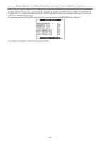
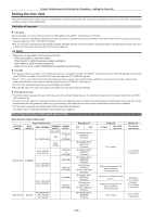
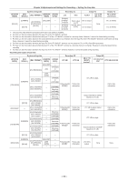
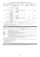
Chapter 4 Adjustments and Settings for Recording - Setting the time data Setting the time data The camera provides time codes, user bits, and date/time (real time) data as time data, and they are recorded in frame in sync with video. They are also recorded as data for clip metadata files. Definition of time data rr Time code Rec run and free run can be switched by the [TC_MD] setting on the [SET01:TC/UB] screen of SmartUI. ffFree run: The time code always advances even when the power is turned off, and it can be handled in the same way as time. It can also be slaved to the time code input to the terminal. ffRec run: The time code advances only during recording. Normally, the time code is recorded as sequential values to the previously recorded clip, and is held even if the power is turned off or the P2 card is replaced. @@NOTE tt Values are not sequential in the following instances: - When a recorded clip has been deleted - When the 24P or 24PA frame rate has been switched to - When 24PN or 30PN has been switched to - When an error such as [REC WARNING] has stopped recording midway rr User bits ffTwo types of user bits are built in: LTC UB (recorded as LTC, and output from the terminal and as LTC of HD SDI signals) and VITC UB (with DVCPRO, recorded in the VIDEO AUX area, and output as VITC of HD SDI signals). ffFor LTC UB, you can select and record each respective user set values, time, year/month/day, with the same value as time codes, camera photo frame rate information, input value of external signals (from the terminal), etc. ffFor VITC UB, the camera photo frame rate information is recorded. ffThe LTC UB value at the start of recording is recorded to the user bits of the clip metadata. rr Date/time (real time) ffThe internal clock measures the year, month, day, and time, and can display these on the viewfinder screen and on the output video from the terminal, etc. ffThe internal clock is used for measuring the free run time code while the power is off and as the time and year/month/day data of the user bits, as well as the reference for file generation times during clip recording, which determine the sorting order of thumbnails and the order of playback. ffIt is also used to generate clip metadata and UMID (Unique Material Identifier). For details, refer to "Setting the date/time of the internal clock" (page 31). Recording and output of time codes and user bits Recording and output of time codes [SYSTEM MODE] System setting state [REC SIGNAL] [REC FORMAT] [CAMERA MODE] [FRAME RATE]*1 [60i], [30P] - [DVCPROHD/60i] (60i) [1FRAME] to [30FRAME] [24P], [24PA] - [AVC‑I100/60i] [AVC‑I50/60i] [1FRAME] - to [30FRAME] [1080‑59.94i] [CAMERA] [30FRAME] [AVC‑I100/30PN] [AVC‑I50/30PN] - Other than [30FRAME] [24FRAME] [AVC‑I100/24PN] [AVC‑I50/24PN] - Other than [24FRAME] [DVCPROHD/60i] [1080‑59.94i] [SDI IN] [AVC‑I100/60i] - - [AVC‑I50/60i] Recording TC LTC VITC [R‑RUN]/[F‑RUN]*2 [DF]/[NDF] 30 frames [R‑RUN]/[F‑RUN]*3 [NDF] fixed 30 frames [R‑RUN]/[F‑RUN]*2 [DF]/[NDF] 30 frames [R‑RUN]/[F‑RUN]*2 [DF]/[NDF] 30 frames [R‑RUN] fixed [DF]/[NDF] At each valid frame 30 frames [R‑RUN]/[F‑RUN]*4 [NDF] fixed 24 frames [R‑RUN] fixed [NDF] fixed At each valid frame 24 frames [R‑RUN]/[F‑RUN]*5 [DF]/[NDF] 30 frames Output TC TC OUT LTC of HD SDI, VITC Display TC TC tc (24/30 conversion) LTC is output. TC: 30 frames tc: 24 frames Matched to recording TC at start of recording 30 frames/second Converted to 30 frames based on LTC. Matched to recording TC at start of recording 30 frames/second LTC is output. Recording TC: 24 frames Playback TC: 24 frames tc: 30 frames TC: 30 frames tc: 24 frames - 63 -
-
 1
1 -
2
-
3
-
4
-
5
-
6
-
7
-
8
-
9
-
10
-
11
-
12
-
13
-
14
-
15
-
16
-
17
-
18
-
19
-
20
-
21
-
22
-
23
-
24
-
25
-
26
-
27
-
28
-
29
-
30
-
31
-
32
-
33
-
34
-
35
-
36
-
37
-
38
-
39
-
40
-
41
-
42
-
43
-
44
-
45
-
46
-
47
-
48
-
49
-
50
-
51
-
52
-
53
-
54
-
55
-
56
-
57
-
 58
58 -
 59
59 -
 60
60 -
 61
61 -
 62
62 -
 63
63 -
 64
64 -
 65
65 -
 66
66 -
 67
67 -
 68
68 -
69
-
70
-
71
-
72
-
73
-
74
-
75
-
76
-
77
-
78
-
79
-
80
-
81
-
82
-
83
-
84
-
85
-
86
-
87
-
88
-
89
-
90
-
91
-
92
-
93
-
94
-
95
-
96
-
97
-
98
-
99
-
100
-
101
-
102
-
103
-
104
-
105
-
106
-
107
-
108
-
109
-
110
-
111
-
112
-
113
-
114
-
115
-
116
-
117
-
118
-
119
-
120
-
121
-
122
-
123
-
124
-
125
-
126
-
127
-
128
-
129
-
130
-
131
-
132
-
133
-
134
-
135
-
136
-
137
-
138
-
139
-
140
-
141
-
142
-
143
-
144
-
145
-
146
-
147
-
148
-
149
-
150
-
151
-
152
-
153
-
154
-
155
-
156
-
157
-
158
-
159
-
160
-
161
-
162
-
163
-
164
-
165
-
166
-
167
-
168
-
169
-
170
-
171
-
172
-
173
-
174
-
175
-
176
-
177
-
178
 |
 |
