Panasonic AG-HPX600PJB Operating Instructions - Page 29
SmartUI display ([HOME] screen)
 |
View all Panasonic AG-HPX600PJB manuals
Add to My Manuals
Save this manual to your list of manuals |
Page 29 highlights
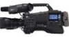
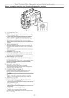
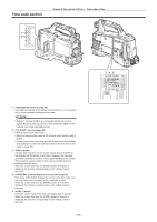
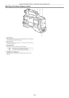
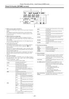
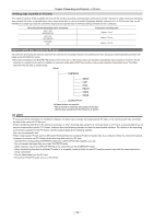
Chapter 2 Description of Parts - SmartUI display ([HOME] screen) SmartUI display ([HOME] screen) 4 5 TC NDF SLAVE P -REC 3 1 MEDIA CH1 A E F 2 BATT CH2 E F 12 6 1 Media remaining space indicator bar Indicates the remaining free space in the P2 card using a 7-segment display. Each segment is equivalent to three minutes, and the decreasing P2 card remaining time is indicated by the segments going out one segment at a time. 2 Battery charge level indicator bar When a battery with a digital indication (% indication) is used, all seven segments up to the F position light if the battery charge level is 70% or higher. When the battery charge level falls below 70%, the segments go out one by one for each 10% drop. 3 Audio channel level meter One segment indicates 2 dB increment, with the smallest indication being −36 dB and the [OVER] indication displayed by ( at the topmost position. Each time you press the button, CH1/CH2, stereo, CH3/CH4 are switched, and the channel display of the level meter is switched together. (page 141) Channels output to the monitor audio are displayed in white dropout. When the stereo is selected, both channels are displayed in white dropout. 4 Time code indications Each time you press the button, the display changes in the order of [CLIP] → [TC] → [tc] → [UB] → [FR] → [CLIP] (viewfinder screen not displayed)* → [CLIP]. * The time code on the viewfinder screen is hidden. [CLIP] [TC] [tc] [UB] [FR] Indicates the counter value in hours:minutes:seconds. Indicates the time code value in hours:minutes:seconds:frames. Indicates the time code value in hours:minutes:seconds:frames. The frame is displayed after converting the frame digit to 24 frames. Indicates the user bits value. Indicates the information of the frame rate at which recording is performed. [60I] 60i interlace mode (60 fields/sec) [60P] 60P progressive mode (60 frames/ sec) [30P] 30P progressive mode (30 frames/ sec) [24P]* 24P progressive mode (24 frames/ sec) [24PA]* 24P advance mode (24 frames/sec) [50I] 50i interlace mode (50 fields/sec) [50P] 50P progressive mode (50 frames/ sec) [25P] 25P progressive mode (25 frames/ sec) * In the case of 24P and 24PA, the sequence number is indicated. [NDF] [DF] [HOLD] [F‑RUN] [R‑RUN] [SLAVE] Indicated when the time code is in the non-drop frame mode. Indicated when the time code is in the drop frame mode. Indicated when the time code generator/read value is held. Indicated when the time code is set to advance continuously regardless of the recording operation. Indicated when the time code is set to advance only during recording. Indicated when the time code is externally locked. 5 Recording mode display [REC] [P‑REC] [i‑REC] [L‑REC] Standard recording When pre-recording mode is set Interval recording setting Loop recording setting 6 Status information Audio level display Audio input At a USB connection Error, card warning display Indicates whether audio CH1/CH3 or CH2/CH4 audio volume and audio level are in the auto adjustment mode. In the auto adjustment mode, [A] is displayed. Indicates the input settings of audio CH1, CH2, CH3, and CH4. Indicated when the [PC MODE] item on the setting menu [PC/USB/LAN] screen is set to [ON], and a device selected at [PC MODE SEL] is connected. ffIn the USB host mode: [USB HOST CONNECTED]/[USB HOST DISCONNECTED] ffIn the USB device mode: [USB DEVICE CONNECTED]/[USB DEVICE DISCONNECTED] Indicates the error code when something has caused an error on the camera. - 29 -
-
 1
1 -
2
-
3
-
4
-
5
-
6
-
7
-
8
-
9
-
10
-
11
-
12
-
13
-
14
-
15
-
16
-
17
-
18
-
19
-
20
-
21
-
22
-
23
-
 24
24 -
 25
25 -
 26
26 -
 27
27 -
 28
28 -
 29
29 -
 30
30 -
 31
31 -
 32
32 -
 33
33 -
 34
34 -
35
-
36
-
37
-
38
-
39
-
40
-
41
-
42
-
43
-
44
-
45
-
46
-
47
-
48
-
49
-
50
-
51
-
52
-
53
-
54
-
55
-
56
-
57
-
58
-
59
-
60
-
61
-
62
-
63
-
64
-
65
-
66
-
67
-
68
-
69
-
70
-
71
-
72
-
73
-
74
-
75
-
76
-
77
-
78
-
79
-
80
-
81
-
82
-
83
-
84
-
85
-
86
-
87
-
88
-
89
-
90
-
91
-
92
-
93
-
94
-
95
-
96
-
97
-
98
-
99
-
100
-
101
-
102
-
103
-
104
-
105
-
106
-
107
-
108
-
109
-
110
-
111
-
112
-
113
-
114
-
115
-
116
-
117
-
118
-
119
-
120
-
121
-
122
-
123
-
124
-
125
-
126
-
127
-
128
-
129
-
130
-
131
-
132
-
133
-
134
-
135
-
136
-
137
-
138
-
139
-
140
-
141
-
142
-
143
-
144
-
145
-
146
-
147
-
148
-
149
-
150
-
151
-
152
-
153
-
154
-
155
-
156
-
157
-
158
-
159
-
160
-
161
-
162
-
163
-
164
-
165
-
166
-
167
-
168
-
169
-
170
-
171
-
172
-
173
-
174
-
175
-
176
-
177
-
178
 |
 |
