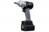
Panasonic EYFMA2C Owner s Manual - Page 14
Attaching or Removing Bit, Attaching Socket Pin type, Removing Socket Pin type, Attaching Socket Pin
 |
View all Panasonic EYFMA2C manuals
Add to My Manuals
Save this manual to your list of manuals |
Page 14 highlights
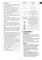
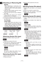
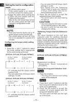
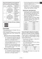
EN Attaching or Removing Bit NOTE: • When attaching or removing a bit, disconnect battery pack from tool or place the switch in the center position (switch lock). 1. Hold the collar of quick connect chuck and pull it out from the tool. 2. Insert the bit into the chuck. Release the collar. 3. The collar will return to its original position when it is released. 4. Pull the bit to make sure it does not come out. 5. To remove the bit, pull out the collar in the same way. CAUTION: • If the collar does not return to its original position or the bit comes out when pulled on, the bit has not been properly attached. Make sure the bit is properly attached before use. EYFLA4A/EYFLA5A/EYFLA7A/EYFLA8A EYFLA4AR/EYFLA5AR/EYFLA7AR/EYFLA8AR 12 mm (15/32") 9 mm - 9.5 mm 6.35 mm (23/64" - 3/8") (1/4") Attaching Socket (Pin type) Remove the socket's rubber ring and pin. [Fig.1] 1 Attach the socket to the tool. 2 Insert the pin. (Taking care to align the pin holes on the socket and tool.) 3 Attach the rubber ring by sliding it into place over the groove. [Fig.2] NOTE: Be sure to attach the rubber ring to prevent the pin from falling out. Removing Socket (Pin type) 1 Remove the rubber ring. 2 Remove the pin. 3 Remove the socket from the tool. [Fig.3] Attaching Socket (Pin-detent) 1 Depress the pin-detent on the square drive. 2 Attach the socket to square drive. 3 Make sure the socket is securely attached to the square drive. [Fig.4] Removing Socket (Pin-detent) 1 Insert a small rod into the hole on the socket. 2 Depress the pin-detent, then detach the socket. [Fig.5] CAUTION: • When attaching a socket to the driver, verify that the socket and pin-detent do not interfere with one another. [Fig.6] • Some sockets may not function well with the driver due to their shape. Avoid use of sockets such as the following: 1 Sockets shaped so that the pindetent makes contact with the side of the socket's pin hole when the socket is attached to the driver. The pin-detent will be subjected to excessive force, possibly damaging it. [Fig.7] 2 Sockets with a pin hole on one side only You may be unable to remove the socket if it is attached in the wrong orientation. [Fig.8] 3 Sockets whose pin holes have beveled edges The socket will not be held in place with sufficient force, so that it may come off during use. [Fig.9] - 14 -
-
 1
1 -
2
-
3
-
4
-
5
-
6
-
7
-
8
-
 9
9 -
 10
10 -
 11
11 -
 12
12 -
 13
13 -
 14
14 -
 15
15 -
 16
16 -
 17
17 -
 18
18 -
 19
19 -
20
-
21
-
22
-
23
-
24
-
25
-
26
-
27
-
28
-
29
-
30
-
31
-
32
-
33
-
34
-
35
-
36
-
37
-
38
-
39
-
40
-
41
-
42
-
43
-
44
-
45
-
46
-
47
-
48
-
49
-
50
-
51
-
52
-
53
-
54
-
55
-
56
-
57
-
58
-
59
-
60
-
61
-
62
-
63
-
64
-
65
-
66
-
67
-
68
-
69
-
70
-
71
-
72
-
73
-
74
-
75
-
76
 |
 |
