Panasonic EYFMA2C Owner s Manual - Page 22
Setting the impact speed, corresponding to the length, of the socket used, EYFLA9, EYFMA2
 |
View all Panasonic EYFMA2C manuals
Add to My Manuals
Save this manual to your list of manuals |
Page 22 highlights
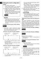
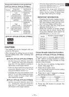
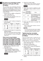
EN Setting the impact speed corresponding to the length of the socket used (EYFLA9, EYFMA2) To set the stable impact speed based on the length of the socket used, do as follows: 1. Set the tool to the configuration mode. (See page 18.) 2. Press button D three times. • The current set value is displayed, and the main unit panel starts flashing. Display: h0 flashing. Battery capacity indicator: The upper and lower bars flash. [Fig.32] 3. Press and buttons as required to change the value. Display h0 h1 h2 Impact Speed Standard Standard socket (high speed) Up to 150 mm socket (medium speed) Up to 250 mm socket (low speed) 4. Press the OK button to accept the new setting. Setting use interval Use interval is set to prevent the screwdriver from continuing its operation when the tool is automatically stopped due to the implementation of the torque correction feature. This setting is valid even when the switch is off. 1. Set the tool to the configuration mode. (See page 18.) [EYFLA4, EYFLA5, EYFLA6, EYFMA1] 2. Press button B. • The main unit panel starts flashing. Display: 0 flashing intermittently. Battery capacity indicator: The middle bar flashes intermittently. [Fig.33] 3. Press and buttons as required to set the time. Operation Display 30 Seconds 3 1 0.1 0 OFF 4. Press OK to confirm the settings. • The control panel stops flashing and lights up to display the torque clutch settings. NOTE: Check the new value after you change the settings. [EYFLA7, EYFLA8, EYFLA9, EYFMA2] 2. Press button D twice. • The current set value is displayed, and the main unit panel starts flashing. Display: U flashing. Battery capacity indicator: The upper and lower bars flash. [Fig.33] 3. Press and as required to change the time. Operation Display U9 U8 U7 U6 U5 U4 U3 U2 U1 U0 U Seconds 3 2.5 2 1.5 1.2 1 0.7 0.5 0.3 0.1 OFF 4. Press the OK button to accept the new setting. • The control panel stops flashing and lights up to display the torque clutch settings. NOTE: Check the new value after you change the settings. - 22 -
-
 1
1 -
2
-
3
-
4
-
5
-
6
-
7
-
8
-
9
-
10
-
11
-
12
-
13
-
14
-
15
-
16
-
 17
17 -
 18
18 -
 19
19 -
 20
20 -
 21
21 -
 22
22 -
 23
23 -
 24
24 -
 25
25 -
 26
26 -
 27
27 -
28
-
29
-
30
-
31
-
32
-
33
-
34
-
35
-
36
-
37
-
38
-
39
-
40
-
41
-
42
-
43
-
44
-
45
-
46
-
47
-
48
-
49
-
50
-
51
-
52
-
53
-
54
-
55
-
56
-
57
-
58
-
59
-
60
-
61
-
62
-
63
-
64
-
65
-
66
-
67
-
68
-
69
-
70
-
71
-
72
-
73
-
74
-
75
-
76
 |
 |
