Panasonic EYFMA2C Owner s Manual - Page 21
Buzzer setting, EYFLA7, EYFLA8, EYFLA9, EYFMA2, LED light setting, Speed control function, Setting
 |
View all Panasonic EYFMA2C manuals
Add to My Manuals
Save this manual to your list of manuals |
Page 21 highlights
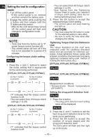
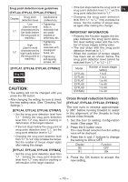
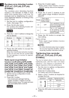
NOTE: • When the remaining time prior to the tightening time is less than 1 hour, the display will alternate between the "set value" and "-1". If the current tightening time remains unchanged and the inspection duration is extended, the new set value must be greater than the current one. When it reaches the set time, the display alternates between the set value and 0. Buzzer setting (EYFLA7, EYFLA8, EYFLA9, EYFMA2) You can select from three buzzer modes. 1. Set the tool to setting configuration mode. (See page 18.) 2. Press the A button twice. The current setting value will be displayed. 3. Press the and buttons to set the desired value. Display Function b0 No buzzer b1 Buzzer accompanying green indicator b2 Buzzer accompanying red indicator 4. Press the OK button to accept the new setting. NOTE: The tool ships with the buzzer mode set to b0 by default. LED light setting (EYFLA7, EYFLA8, EYFLA9, EYFMA2) You can select from two LED light modes. 1. Set the tool to setting configuration mode. (See page 18.) 2. Press the B button once. The current setting value will be displayed. 3. Press the and buttons to set the desired value. Display d1 d2 Function Linked to LED light button Linked to trigger switch operation 4. Press the OK button to accept the new setting. NOTE: EN The tool ships with the LED light mode set to d1 by default. Speed control function (EYFLA7, EYFLA8, EYFLA9, EYFMA2) The speed (RPM) can be changed with the amount of depression of the trigger. 1. Set the tool to setting configuration mode. (See page 18.) 2. Press the B button three times. The setting value will be displayed. 3. Press the and buttons to set the desired value. Operation P0 P1 Function Speed control ON Speed control OFF 4. Press the OK button to accept the new setting. Setting the undetect time (EYFLA7, EYFLA8, EYFLA9, EYFMA2) To set the time to undetect the function of "snug point detection level" from the start tightening, do as follows. 1. Set the tool to the configuration mode. (See page 18.) 2. Press button A three times. • The current set value is displayed, and the main unit panel starts flashing. Display: J0 flashing. Battery capacity indicator: The upper and lower bars flash. [Fig.31] 3. Press and buttons as required to change the time. Operation Display 30 Seconds 3 1 0.1 J0 OFF 4. Press the OK button to accept the new setting. - 21 -
-
 1
1 -
2
-
3
-
4
-
5
-
6
-
7
-
8
-
9
-
10
-
11
-
12
-
13
-
14
-
15
-
 16
16 -
 17
17 -
 18
18 -
 19
19 -
 20
20 -
 21
21 -
 22
22 -
 23
23 -
 24
24 -
 25
25 -
 26
26 -
27
-
28
-
29
-
30
-
31
-
32
-
33
-
34
-
35
-
36
-
37
-
38
-
39
-
40
-
41
-
42
-
43
-
44
-
45
-
46
-
47
-
48
-
49
-
50
-
51
-
52
-
53
-
54
-
55
-
56
-
57
-
58
-
59
-
60
-
61
-
62
-
63
-
64
-
65
-
66
-
67
-
68
-
69
-
70
-
71
-
72
-
73
-
74
-
75
-
76
 |
 |
