Panasonic KXP1121E Operating Instructions - Page 38
Printing Area, Fanfold Paper
 |
View all Panasonic KXP1121E manuals
Add to My Manuals
Save this manual to your list of manuals |
Page 38 highlights
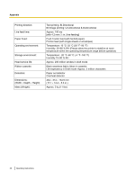
Appendix Printing Area Fanfold Paper B C 1st character Printing area A Paper perforations A Printing area D Fanfold Paper A 25.4 mm (1 in.) B 17.8 mm (0.7 in.) C 8.38 mm (0.33 in.) D 25.4 mm (1 in.) A. Value A indicates the area near the paper perforations where the quality may not be optimum. B. Value B indicates the maximum distance between the sprockets and first printable character. (When the left tractor is set on the left end and the margin is set to 0.) C. Value C indicates the area from the top edge of the paper to the top of the first printed character. D. Value D indicates the position where paper out is detected and printing may not be optimum. 38 Operating Instructions
-
 1
1 -
2
-
3
-
4
-
5
-
6
-
7
-
8
-
9
-
10
-
11
-
12
-
13
-
14
-
15
-
16
-
17
-
18
-
19
-
20
-
21
-
22
-
23
-
24
-
25
-
26
-
27
-
28
-
29
-
30
-
31
-
32
-
 33
33 -
 34
34 -
 35
35 -
 36
36 -
 37
37 -
 38
38 -
 39
39 -
 40
40 -
 41
41 -
 42
42 -
 43
43
 |
 |

Printing Area
Fanfold Paper
1st character
Paper perforations
Printing area
Printing area
A
D
B
A
C
Fanfold Paper
A
25.4 mm (1 in.)
B
17.8 mm (0.7 in.)
C
8.38 mm (0.33 in.)
D
25.4 mm (1 in.)
A.
Value A indicates the area near the paper perforations where the quality may not be optimum.
B.
Value B indicates the maximum distance between the sprockets and first printable character. (When
the left tractor is set on the left end and the margin is set to 0.)
C.
Value C indicates the area from the top edge of the paper to the top of the first printed character.
D.
Value D indicates the position where paper out is detected and printing may not be optimum.
38
Operating Instructions
Appendix