Pioneer DEQ 9200 Owners Manual - Page 11
Mounting, Example, Fixing, Front, Panel
 |
UPC - 012562290973
View all Pioneer DEQ 9200 manuals
Add to My Manuals
Save this manual to your list of manuals |
Page 11 highlights
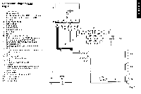
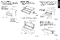
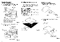
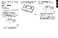
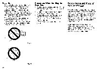
Mounting Example 1: Fasten the control unit with Velcro tape • Thoroughly wipe off the surface before affixing the Velcro tape. Velcro tape (Soft surface) Remove the oil-paper from the back and attach. Console, etc. Mounting base Velcro tape (Round surface) Remove the oil-paper from the back and attach. Fig. 9 Mounting Example 2: Installation of mounting bracket 1. Temporarily assemble the bracket. (Fig. 10) 0 O 0 7 O Screw O (4 x 6 mm) Fig. 10 2. Use screws (3 x 4 mm) to install the bracket to the mounting base. (Fig. 11) I) Screw (3 x 4 mm) 0 o 0 O 6 I 0 3. Use wood screws (4 x 16 mm) to install the bracket to the console. Adjust the angle so that the control unit is easy to see and fix with adjusting screws. (Fig. 12) Console, etc. Drill 2 to 2.5 mm diameter holes r Wood screw (4 x 16 trim) 0 O .,i O O O Mounting base Fig. 12 Fixing the Front Panel The front panel can be fixed to the mounting base using screws in the procedure described in Examples 1 and 2. (Fig. 13) Mounting base Screw Mounting base Fig. 11 Front panel Fig. 13 11
-
 1
1 -
2
-
3
-
4
-
5
-
 6
6 -
 7
7 -
 8
8 -
 9
9 -
 10
10 -
 11
11 -
 12
12 -
 13
13 -
 14
14 -
 15
15 -
 16
16 -
17
-
18
-
19
-
20
-
21
-
22
-
23
-
24
-
25
-
26
-
27
-
28
-
29
-
30
-
31
-
32
-
33
-
34
-
35
-
36
-
37
-
38
 |
 |
