Pioneer DEQ 9200 Owners Manual - Page 8
Connection, Diagram
 |
UPC - 012562290973
View all Pioneer DEQ 9200 manuals
Add to My Manuals
Save this manual to your list of manuals |
Page 8 highlights
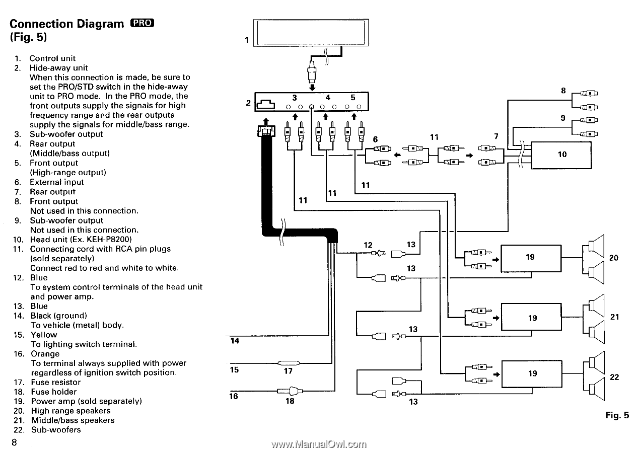
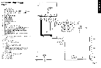
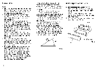
Connection Diagram PRO (Fig. 5) 1. Control unit 2. Hide-away unit When this connection is made, be sure to set the PRO/STD switch in the hide-away unit to PRO mode. In the PRO mode, the front outputs supply the signals for high frequency range and the rear outputs supply the signals for middle/bass range. 3. Sub-woofer output 4. Rear output (Middle/bass output) 5. Front output (High-range output) 6. External input 7. Rear output 8. Front output Not used in this connection. 9. Sub-woofer output Not used in this connection. 10. Head unit (Ex. KEH-P8200) 11. Connecting cord with RCA pin plugs (sold separately) Connect red to red and white to white. 12. Blue To system control terminals of the head unit and power amp. 13. Blue 14. Black (ground) To vehicle (metal) body. 15. Yellow To lighting switch terminal. 16. Orange To terminal always supplied with power regardless of ignition switch position. 17. Fuse resistor 18. Fuse holder 19. Power amp (sold separately) 20. High range speakers 21. Middle/bass speakers 22. Sub-woofers 8 1 2 14 15 16 3 4 5 0 000 0 0 0 • • • 6 11 11 11 11 =Caz- -CMD- 12 13 13 13 17 1E> EX} 18 13 8 9 7 10 19 20 ti 19 21 19 22 Fig. 5
-
 1
1 -
2
-
 3
3 -
 4
4 -
 5
5 -
 6
6 -
 7
7 -
 8
8 -
 9
9 -
 10
10 -
 11
11 -
 12
12 -
 13
13 -
14
-
15
-
16
-
17
-
18
-
19
-
20
-
21
-
22
-
23
-
24
-
25
-
26
-
27
-
28
-
29
-
30
-
31
-
32
-
33
-
34
-
35
-
36
-
37
-
38
 |
 |