Pioneer PRO-1410HD Owner's Manual - Page 6
Front View, WARNING, Rear View/ Terminal Board - speakers
 |
View all Pioneer PRO-1410HD manuals
Add to My Manuals
Save this manual to your list of manuals |
Page 6 highlights
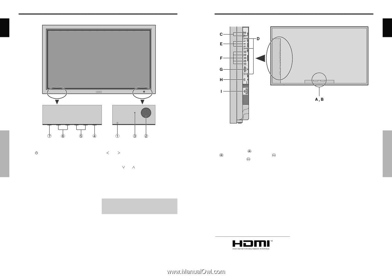
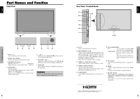
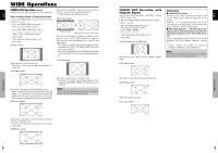
Part Names and Function Front View Rear View/ Terminal Board English English Part Names and Function q Power ( ) Turns the monitor's power on and off. w Remote sensor window Receives the signals from the remote control. e STANDBY/ON indicator When the power is on Lights green. When the power is in the standby mode ... Lights red. r INPUT/EXIT Switches the input. The available inputs depend on the setting of "BNC INPUT" and "RGB SELECT". Functions as the EXIT buttons in the On-Screen Display (OSD) mode. t and Functions as the CURSOR buttons in the OnScreen Display (OSD) mode. y VOLUME and Adjusts the volume. Functions as the CURSOR (L/ M) buttons in the On-Screen Display (OSD) mode. u MENU/SET Sets the On-Screen Display (OSD) mode and displays the main menu. WARNING The Power on/off switch does not disconnect the plasma display completely from the supply mains. 4 En Part Names and Function A AC IN Connect the included power cord here. B EXT SPEAKER L and R Connect speakers (optional) here. Maintain the correct polarity. Connect the (positive) speaker wire to the EXT SPEAKER terminal and the (negative) speaker wire to the EXT SPEAKER terminal on both LEFT and RIGHT channels. Please refer to your speaker's owner's manual. C VIDEO1, 2, 3 (BNC, RCA, S-Video) Connect VCR's, DVD's or Video Cameras, etc. here. D AUDIO1, AUDIO2, AUDIO3 These are audio input terminals. The input is selectable. Set which video image to allot them from the SOUND menu screen. E COMPONENT 1 Connect DVD's, High Definition or Laser Discs, etc. here. F PC2/ COMPONENT2 PC2: You can connect an analog RGB signal and the syncronization signal. COMPONENT2: You can connect DVDs, High Definition sources, Laser Discs, etc. here. This input can be set for use with an RGB or component source (see page 19). G PC1 (D-Sub) Connect an analog RGB signal from a computer, etc. here. H HDMI Connect a digital signal from a source with a HDMI output. See page 30 for the details of Supported Signals. I RS-232C (D-Sub) Never connect any component to this connector without first consulting your Pioneer installation technician. This connector is used for plasma display setup adjustments. HDMI, the HDMI logo and High-Definition Multimedia Interface are trademarks or registered trademarks of HDMI Licensing LLC. 5 En
-
 1
1 -
 2
2 -
 3
3 -
 4
4 -
 5
5 -
 6
6 -
 7
7 -
 8
8 -
 9
9 -
 10
10 -
 11
11 -
 12
12 -
13
-
14
-
15
-
16
-
17
-
18
-
19
 |
 |