Pioneer SC-27 Owner's Manual - Page 42
Connecting an HDMI-equipped component to the front panel input, Connect your computer to the, RS-232C
 |
UPC - 012562957487
View all Pioneer SC-27 manuals
Add to My Manuals
Save this manual to your list of manuals |
Page 42 highlights
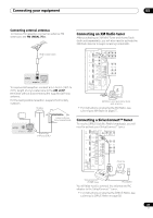
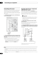
03 Connecting your equipment • Connect your computer to the RS-232C jack on the rear panel of the receiver. Make sure that the receiver and all connected components are switched off and disconnected from the power outlet when you do this.1 Use a commercially-available cable to connect the RS232C jack on your computer to the 9-pin RS-232C jack on this receiver. See the documentation provided with the Advanced MCACC application for more information. HDMI OUT 1 (KURO LINK ) OUT 2 XM IN COAXIAL ASSIGNABLE IN 1 (DVD) IN 2 (CD) BD IN IN 1 IN 2 IN 3 ASSIGNABLE 1-3 LAN (10/100) IN 3 (VIDEO 2) IN 1 (TV/SAT) IN 2 (DVR) IN 3 (VIDEO1) IN 4 (CD-R) ASSIGNABLE OUT 1 OUT 2 OPTICAL 12 V 1 IN 1 TRIGGER (OUTPUT 12V (DVD) (D TOTAL 50 mA MAX) 2 PR PB Y ZONE 2 OUT P SIRIUS IN IR IN 1 IN 2 OUT IN CONTROL OUT VIDEO ZONE 2 ZONE 3 OUT OUT L R SPEAKERS SELECTABLE SEE INSTRUCTION MANUAL CAUTION SPEAKER IMPE ATTENTI ENCEINTE D'IM SELECTABL VOIR LE MOD D'EMPLOI RS-232C Connecting an HDMI-equipped component to the front panel input There is an HDMI input terminal on the front panel. High quality pictures can be viewed via the receiver simply by connecting an HDMI-equipped video camera with a single HDMI cable. HDMI-equipped components other than video cameras can also be connected to this terminal. • Push down on the lower portion of the front panel door to access the front panel input. • Select this input using HDMI, INPUT SELECT (remote) or the INPUT SELECTOR dial (front panel) to select HDMI 4. CONTROL ON/OFF TUNER EDIT BAND AUTO SURR/ALC/ HOME STANDARD ADVANCED STEREO STREAM DIRECT THX SURROUND SURROUND HDMI 4 VIDEO CAMERA iPod iPhone USB MULTI-ZONE SPEAKERS MCACC SETUP MIC PHONES This receiver RS-232C Personal computer Video camera, etc. Note 1 The various parameters, the reverb characteristics data and group delay characteristics data used for display on the computer are not cleared when the power is turned off (see Output PC on page 120). 42 en
-
 1
1 -
2
-
3
-
4
-
5
-
6
-
7
-
8
-
9
-
10
-
11
-
12
-
13
-
14
-
15
-
16
-
17
-
18
-
19
-
20
-
21
-
22
-
23
-
24
-
25
-
26
-
27
-
28
-
29
-
30
-
31
-
32
-
33
-
34
-
35
-
36
-
 37
37 -
 38
38 -
 39
39 -
 40
40 -
 41
41 -
 42
42 -
 43
43 -
 44
44 -
 45
45 -
 46
46 -
 47
47 -
48
-
49
-
50
-
51
-
52
-
53
-
54
-
55
-
56
-
57
-
58
-
59
-
60
-
61
-
62
-
63
-
64
-
65
-
66
-
67
-
68
-
69
-
70
-
71
-
72
-
73
-
74
-
75
-
76
-
77
-
78
-
79
-
80
-
81
-
82
-
83
-
84
-
85
-
86
-
87
-
88
-
89
-
90
-
91
-
92
-
93
-
94
-
95
-
96
-
97
-
98
-
99
-
100
-
101
-
102
-
103
-
104
-
105
-
106
-
107
-
108
-
109
-
110
-
111
-
112
-
113
-
114
-
115
-
116
-
117
-
118
-
119
-
120
-
121
-
122
-
123
-
124
-
125
-
126
-
127
-
128
-
129
-
130
-
131
-
132
-
133
-
134
-
135
-
136
-
137
-
138
-
139
-
140
-
141
-
142
-
143
-
144
-
145
-
146
-
147
-
148
-
149
-
150
-
151
-
152
-
153
-
154
 |
 |
