Poulan PPBV25 Owner Manual - Page 4
Assembly - pro
 |
View all Poulan PPBV25 manuals
Add to My Manuals
Save this manual to your list of manuals |
Page 4 highlights
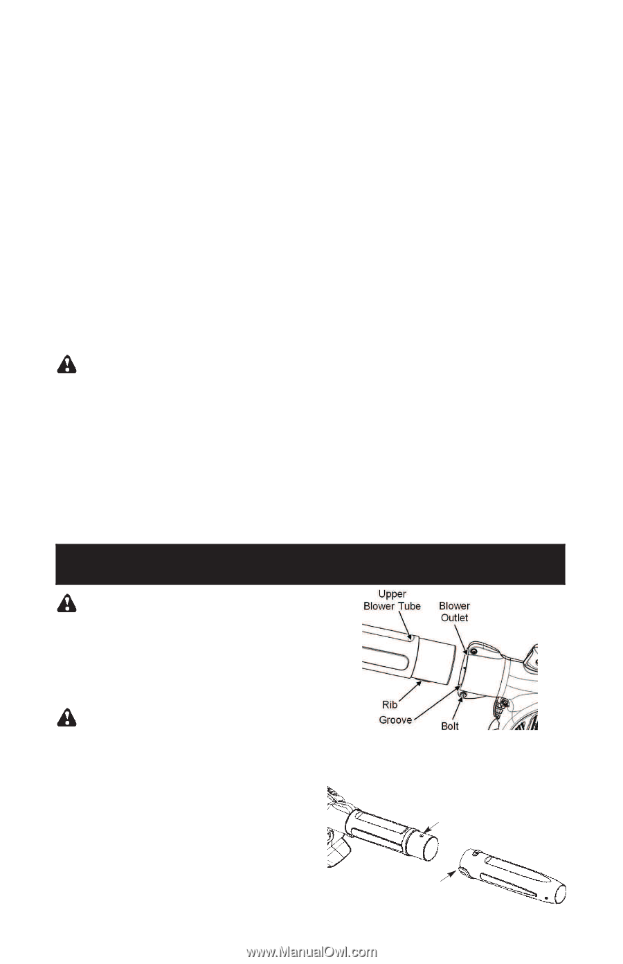
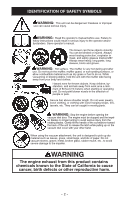
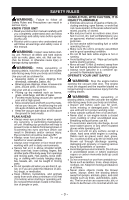
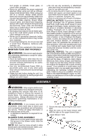
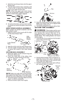
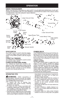
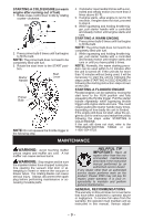
hurt people or animals, break glass, or cause other damage. D Never run unit without the proper equipment attached. When using your unit as a blower, always install blower tubes. When using your unit as a vacuum, always install vacuum tubes and vacuum bag assembly. Make sure vacuum bag assembly is completely zipped. D Check air intake opening, blower tubes, vacuum tubes, and elbow tube frequently, always with engine stopped and spark plug disconnected. Keep vents and discharge tubes free of debris which can accumulate and restrict proper air flow. D Never place any object in the air intake opening as this could restrict proper air flow and cause damage to the unit. D Never use for spreading chemicals, fertilizers, or other substances which may contain toxic materials. D To avoid spreading fire, do not use near leaf or brush fires, fireplaces, barbecue pits, ashtrays, etc. D Use only for jobs explained in this manual. MAINTAIN YOUR UNIT PROPERLY WARNING: Disconnect spark plug be- fore performing maintenance except for carburetor adjustments. D Have all maintenance other than the rec- ommended procedures described in the instruction manual performed by an authorized service dealer. D Use only recommended Poulan PRO replacement parts; use of any other parts may void your warranty and cause damage to your unit. D Empty fuel tank before storing the unit. Use up fuel left in carburetor by starting engine and letting it run until it stops. D Do not use any accessory or attachment other than those recommended by manufac- turer for use with your unit. D Do not store the unit or fuel in a closed area where fuel vapors can reach sparks or an open flame from hot water heaters, electric motors or switches, furnaces, etc. D Store in a dry area out of reach of children. SPECIAL NOTICE: Exposure to vibrations through prolonged use of gasoline powered hand tools could cause blood vessel or nerve damage in the fingers, hands, and joints of people prone to circulation disorders or abnormal swelling. Prolonged use in cold weather has been linked to blood vessel damage in otherwise healthy people. If symptoms occur such as numbness, pain, loss of strength, change in skin color or texture, or loss of feeling in the fingers, hands, or joints, discontinue the use of this tool and seek medical attention. An antivibration system does not guarantee the avoidance of these problems. Users who operate power tools on a continual and regular basis must monitor closely their physical condition and the condition of this tool. SPECIAL NOTICE: This unit is equipped with a temperature limiting muffler and spark arresting screen which meets the requirements of California Codes 4442 and 4443. All U.S. forest land and the states of California, Idaho, Maine, Minnesota, New Jersey, Oregon, and Washington require by law that many internal combustion engines be equipped with a spark arresting screen. If you operate in a locale where such regulations exist, you are legally responsible for maintaining the operating condition of these parts. Failure to do so is a violation of the law. Refer to the MAINTENANCE section for information on maintenance of the muffler and spark arresting screen. ASSEMBLY WARNING: Stop engine and be sure the impeller blades have stopped turning before opening the vacuum inlet door or attempting to insert or remove the vacuum or blower tubes. The rotating blades can cause serious injury. Always disconnect the spark plug before performing maintenance or accessing movable parts. WARNING: If you receive your unit assembled, check each step to insure your unit is properly assembled and all fasteners are secure. Follow all safety information in the manual and on the unit. D A standard screwdriver is required for as- sembly. BLOWER TUBE ASSEMBLY 1. Align the rib on the upper blower tube with the groove in the blower outlet; slide the tube into place. NOTE: Bolt must be loose enough to allow blower tube to be inserted in blower outlet. Loosen bolt by turning counterclockwise. 2. Secure the tube by turning the bolt clockwise. 3. Align the slots on the lower blower tube with the tabs on the upper blower tube. Upper Blower Tube Tab Lower Blower Tube Slot -- 4 --
-
 1
1 -
 2
2 -
 3
3 -
 4
4 -
 5
5 -
 6
6 -
 7
7 -
 8
8 -
 9
9 -
 10
10 -
11
-
12
-
13
-
14
-
15
-
16
-
17
-
18
-
19
-
20
-
21
-
22
-
23
-
24
-
25
-
26
-
27
-
28
-
29
-
30
-
31
-
32
-
33
-
34
-
35
-
36
-
37
-
38
-
39
-
40
-
41
-
42
-
43
-
44
 |
 |