Poulan PPBV25 Owner Manual - Page 5
High--speed Nozzle Assembly, Vacuumbagassembly, Vacuumtube Assembly
 |
View all Poulan PPBV25 manuals
Add to My Manuals
Save this manual to your list of manuals |
Page 5 highlights
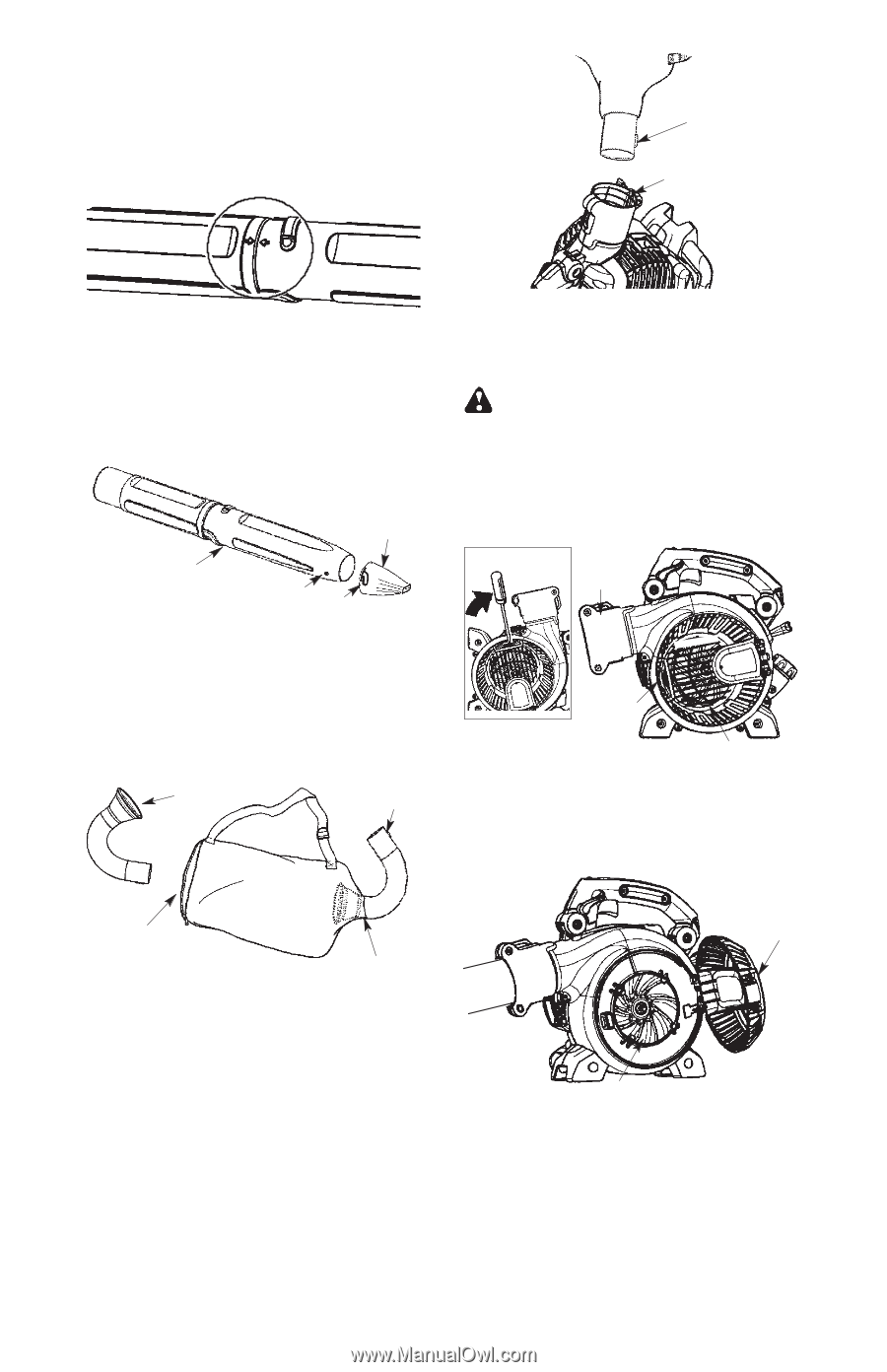
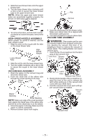
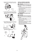
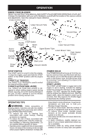
4. Slide the lower blower tube onto the upper blower tube. 5. Turn the lower blower tube clockwise until a click is felt to secure the lower blower tube to the upper blower tube. NOTE: When the upper and lower blower tubes are assembled together properly, the arrows on both tubes will be aligned. Rib Groove 6. To remove the tubes, turn the bolt counterclockwise to loosen the tubes; remove the tubes. HIGH--SPEED NOZZLE ASSEMBLY When greater air speed is desired, use the high--speed nozzle. 1. Align the slots on the nozzle with the tabs on the lower blower tube. High-Speed Nozzle Lower Blower Tube Tab Slot 2. Slide the nozzle onto the lower blower tube. 3. Turn the nozzle clockwise until a click is felt to secure the nozzle to the lower blower tube. VACUUM BAG ASSEMBLY 1. Open the zipper on the vacuum bag and insert the elbow tube. 2. Push the small end of the elbow tube through the small opening in the bag. Elbow Tube Rib Zipper Opening Small Opening NOTE: Make sure edge of the small opening is flush against the flared area of the elbow tube, and the rib on the elbow tube is on the bottom. 3. Close the zipper on the bag. Make sure the zipper is closed completely. 4. Remove blower tubes from engine. 5. Insert the elbow tube into the blower outlet. Make sure elbow tube rib is aligned with the blower outlet groove. 6. Turn bolt clockwise to secure elbow tube. VACUUM TUBE ASSEMBLY WARNING: Stop engine and be sure the impeller blades have stopped turning before opening the vacuum inlet door or attempting to insert or remove the vacuum or blower tubes. The rotating blades can cause serious injury. 1. Insert the tip of a screwdriver into the latch area of the vacuum inlet. Latch Area Blower Outlet Latch Area Vacuum Inlet Cover 2. Gently tilt the handle of the screwdriver to- ward the front of the unit to release the latch while pulling up on the vacuum inlet cover with your other hand. 3. Hold the vacuum inlet cover open until upper vacuum tube is installed. Vacuum Inlet Cover c Vacuum Inlet -- 5 --
-
 1
1 -
 2
2 -
 3
3 -
 4
4 -
 5
5 -
 6
6 -
 7
7 -
 8
8 -
 9
9 -
 10
10 -
 11
11 -
12
-
13
-
14
-
15
-
16
-
17
-
18
-
19
-
20
-
21
-
22
-
23
-
24
-
25
-
26
-
27
-
28
-
29
-
30
-
31
-
32
-
33
-
34
-
35
-
36
-
37
-
38
-
39
-
40
-
41
-
42
-
43
-
44
 |
 |