ProForm 4.0 Rt Bike English Manual - Page 13
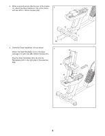
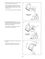
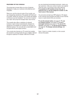
Attach the Front Upright Cover 58 to
 |
View all ProForm 4.0 Rt Bike manuals
Add to My Manuals
Save this manual to your list of manuals |
Page 13 highlights
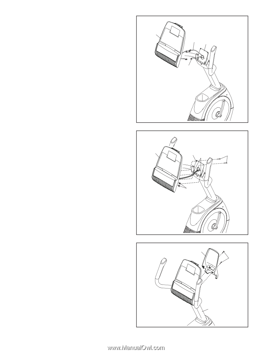
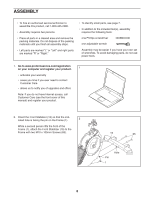
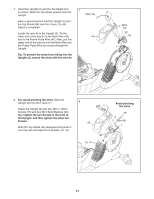
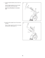
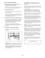
11. Untie and discard the wire ties on the Main Wire (43) and the Frame Pulse Wire (42). While a second person holds the Console (4) near the Upright (2), connect the wires on the Console to the Main Wire (43) and to the Frame Pulse Wire (42). Then, insert the excess wires into the Upright (2). 11 4 43 2 42 Avoid pinching the wires 12. Tip: Avoid pinching the wires. Locate the two console screws in the back of the Console (4). Slide the console screws upward into the indicated slots in the Upright (2). Then, attach the Console (4) to the Upright (2) with two M4 x 16mm Screws (77). 12 4 2 Slots 77 Screws Avoid pinching the wires 13. Identify the Front Upright Cover (58) and orient it as shown. 13 Attach the Front Upright Cover (58) to the Upright (2) with two M4 x 16mm Screws (77). 58 77 2 13
-
 1
1 -
2
-
3
-
4
-
5
-
6
-
7
-
 8
8 -
 9
9 -
 10
10 -
 11
11 -
 12
12 -
 13
13 -
 14
14 -
 15
15 -
 16
16 -
 17
17 -
 18
18 -
19
-
20
-
21
-
22
-
23
-
24
-
25
-
26
-
27
-
28
-
29
-
30
-
31
-
32
 |
 |