ProForm 4.0 Rt Bike English Manual - Page 7
Part Identification Chart
 |
View all ProForm 4.0 Rt Bike manuals
Add to My Manuals
Save this manual to your list of manuals |
Page 7 highlights
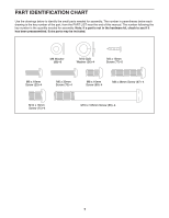
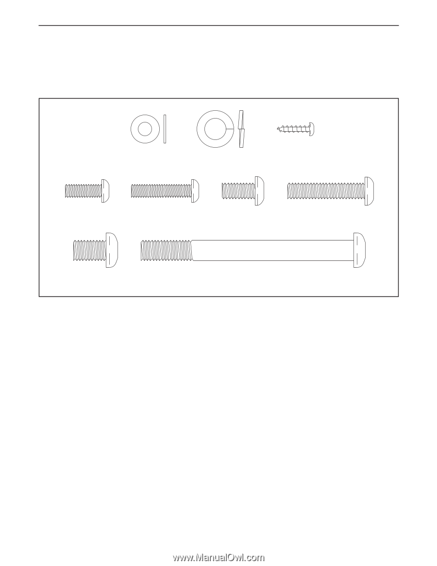
PART IDENTIFICATION CHART Use the drawings below to identify the small parts needed for assembly. The number in parentheses below each drawing is the key number of the part, from the PART LIST near the end of this manual. The number following the key number is the quantity needed for assembly. Note: If a part is not in the hardware kit, check to see if it has been preassembled. Extra parts may be included. M6 Washer (88)-8 M10 Split Washer (36)-4 M4 x 16mm Screw (77)-5 M6 x 18mm Screw (25)-4 M6 x 30mm Screw (70)-4 M8 x 16mm Screw (69)-4 M8 x 38mm Screw (67)-4 M10 x 16mm Screw (75)-4 M10 x 105mm Screw (65)-4 7
-
 1
1 -
 2
2 -
 3
3 -
 4
4 -
 5
5 -
 6
6 -
 7
7 -
 8
8 -
 9
9 -
 10
10 -
 11
11 -
 12
12 -
13
-
14
-
15
-
16
-
17
-
18
-
19
-
20
-
21
-
22
-
23
-
24
-
25
-
26
-
27
-
28
-
29
-
30
-
31
-
32
 |
 |
7
M10 x 105mm Screw (65)–4
M10 x 16mm
Screw (75)–4
M8 x 16mm
Screw (69)–4
M6 Washer
(88)–8
M10 Split
Washer (36)–4
M4 x 16mm
Screw (77)–5
M6 x 18mm
Screw (25)–4
M6 x 30mm
Screw (70)–4
M8 x 38mm Screw (67)–4
Use the drawings below to identify the small parts needed for assembly. The number in parentheses below each
drawing is the key number of the part, from the PART LIST near the end of this manual. The number following the
key number is the quantity needed for assembly.
Note: If a part is not in the hardware kit, check to see if it
has been preassembled. Extra parts may be included.
PART IDENTIFICATION CHART