RCA 32V434T User Guide - Page 10

Connecting - reviews

Page 10 highlights

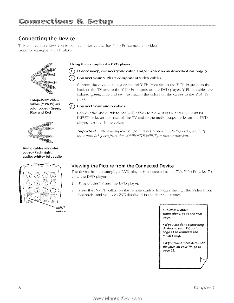
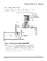
Connecting the Device This connection aJJows V. ou to connect a device that ha.S _• Pb Pr (component jacks, for examp]e, a I)\.'D p]ayer. vklco) Component Video cables (Y Pb Pr) are color coded- Green, Blue and Red Using the example of a D_¢I) player: if necessary, coln_ect your cable and/or antenna as described on page 5. Connect your Y Pb Pr component video cables. Connect three video c_l>k,s or spc_ci_HY Pl) Pr c:_l)]cs to the Y Pb Pr jacks on the back of the T\.' and to the Y Pb Pr OUtl)UtSon the I)Vl) p]ayer. Y Pb Pr cables are co]ored green, blue and red. Just match the colors on the cables to the Y Pb Pr jacks. Connect your audio cables. Connect the audio (white and red) cab]es to the A[H)IO R and L (COMPOSITE INPUT) jacks on the back of the T\" and to the au(lio output jacks on the DVI) player. Just match the colors. Iml_ortattt - _:'b_,iz zlsilzg I_, Cbl'Jzpo_z_,izl _,ic!_,o i_?pzll () Pb P

  • 1
  • 2
  • 3
  • 4
  • 5
  • 6
  • 7
  • 8
  • 9
  • 10
  • 11
  • 12
  • 13
  • 14
  • 15
  • 16
  • 17
  • 18
  • 19
  • 20
  • 21
  • 22
  • 23
  • 24
  • 25
  • 26
  • 27
  • 28
  • 29
  • 30
  • 31
  • 32
  • 33
  • 34
  • 35
  • 36
  • 37
  • 38
  • 39
  • 40
  • 41
  • 42
  • 43
  • 44
  • 45
  • 46
  • 47
  • 48

Connecting
the
Device
.
S
This connection
aJJows Vou to connect
a device
that
ha.
_ Pb Pr (component
vklco)
jacks, for examp]e,
a I)\.'D p]ayer.
Component
Video
cables
(Y Pb Pr) are
color
coded-
Green,
Blue
and
Red
Using
the
example
of
a
D_¢I)
player:
if necessary,
coln_ect
your
and/or
antenna
as
on
page
5.
cable
described
Connect
Y Pb
Pr
video
cables.
your
component
Connect
three
video
c_l>k,s or spc_ci_HY Pl) Pr c:_l)]cs to the
Y Pb Pr jacks
on the
back
of the T\.' and
to the
Y Pb Pr OUtl)UtSon the
I)Vl)
p]ayer.
Y Pb Pr cables
are
co]ored
green,
blue
and
red. Just
match
the
colors
on the
cables
to the Y Pb Pr
jacks.
Connect
audio
cables.
your
Connect
the
audio
(white
and
red)
cab]es
to the A[H)IO
R
and
L (COMPOSITE
INPUT)
jacks on the
back
of the
T\" and to the
au(lio
output
jacks
on the
DVI)
player.
Just
match
the
colors.
Iml_ortattt
-
_:'b_,iz zlsilzg
I_,
Cbl'Jzpo_z_,izl _,ic!_,o
i_?pzll ()
Pb P<)jc_cks,
_se
oll{y
lh_
A
liclio
lg/L.jg_( /.s.i}.onz
I/_,
C011PO57Tl,/
I.XT)_
'7_for
lh is COllll{_(/iOll.
Audio
cables
are color
coded-
Red=
right
audio;
white=
left
audio
iNPUT
ANTENNA
PRESETS
SOUND
_
SKiP
INPUT
button
Viewing
the
Picture
from
the
Connected
Device
The device
in this cx;_mp]_,,
;_
player,
is c'onncc'tcd
to the
TV's Y Pb Pr jacks. To
view the
I)VI)
[)layer:
1.
Turn on the
T\.' and
the
I)VI) p]ayer.
2.
Press
the INPUT button
on the reIllot<_ contro]
to toggle
through
the Video
Input
Channe]s
until you see
CITD
disp]ayed
in the
channe]
banner.
To
review
other
connections,
go
to the next
page.
If you
are
done
connecting
devices
to your
TV, go to
page
11 to complete
the
Initial
Setup.
If you
want
more
details
of
the jacks
on your
TV, go
to
page
13.
Chapter
1