Ricoh IS760 Operating Instructions - Page 12
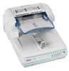
Background Panel for Exposure, USB 2.0 Interface Connector - rollers
 |
View all Ricoh IS760 manuals
Add to My Manuals
Save this manual to your list of manuals |
Page 12 highlights
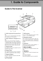
Guide to Components 1 1. Pressure Panel Holds the originals down on the Exposure Glass. 2. Background Panel for Exposure Glass Panel to set the background color for the original in black or white when you place the original on the exposure glass. ⇒ p.54 "Changing the Color of the Background Panel for the Exposure Glass" 3. ADF Exposure Glass Scans the originals when they are loaded by the ADF. 4. Exposure Glass Set the original here when you do not use the ADF scanning. 5. ADF Cover Open when clearing the misfed originals or cleaning the rollers. ADC003S 6. Lock Screw This is to lock the scanning parts inside when you transport this machine. Remove this screw when you set up this machine. 7. USB 2.0 Interface Connector Used for connection of an USB cable. The USB interface board is alternatively used with the optional IEEE1394 interface board. 8. Lock Lever Set this lever to the "Lock" position when you transport this machine. 9. SCSI Interface Connector Used for connection of a SCSI Cable. 10. SD Card Slot Used for an authorized customer engineer's maintenance only. 11. Power Connector For connection of the bundled AC power code. 8
-
 1
1 -
2
-
3
-
4
-
5
-
6
-
 7
7 -
 8
8 -
 9
9 -
 10
10 -
 11
11 -
 12
12 -
 13
13 -
 14
14 -
 15
15 -
 16
16 -
 17
17 -
18
-
19
-
20
-
21
-
22
-
23
-
24
-
25
-
26
-
27
-
28
-
29
-
30
-
31
-
32
-
33
-
34
-
35
-
36
-
37
-
38
-
39
-
40
-
41
-
42
-
43
-
44
-
45
-
46
-
47
-
48
-
49
-
50
-
51
-
52
-
53
-
54
-
55
-
56
-
57
-
58
-
59
-
60
-
61
-
62
-
63
-
64
-
65
-
66
-
67
-
68
-
69
-
70
-
71
-
72
-
73
-
74
-
75
-
76
-
77
-
78
-
79
-
80
-
81
-
82
-
83
-
84
-
85
-
86
-
87
-
88
-
89
-
90
-
91
-
92
-
93
-
94
-
95
-
96
 |
 |
