Ryobi RYi4022X Operation Manual - Page 16

Features, Assembly

Page 16 highlights

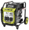
FEATURES OIL CAP/DIPSTICK Remove the oil fill cap to check and add lubricant to the generator when necessary. OIL DRAIN PLUG When changing the engine lubricant, unscrew and remove the oil drain plug to allow old engine lubricant to be drained. RESET BUTTON The reset button is used to restore power if an overload occurs. To restore power, remove the last electrical load added, then depress the reset button. STARTER GRIP AND ROPE The starter grip and rope is used (along with the engine switch) to start the generator's engine. ASSEMBLY UNPACKING This product requires assembly.  Carefully cut the box down the sides then remove the machine and any accessories from the box. Make sure that all items listed in the Loose Parts List are included. NOTE: This machine is heavy and requires a minimum of two people to lift. To avoid back injury, lift with your legs and not your back. WARNING: Do not use this product if any parts in the Loose Parts List are already assembled to your product when you unpack it. Parts on this list are not assembled to the product by the manufacturer and require customer installation. Use of a product that may have been improperly assembled could result in serious personal injury.  Inspect the unit carefully to make sure no damage occurred during shipping.  Do not discard the packing material until you have ­carefully inspected and satisfactorily operated the ­product.  If any parts are damaged or missing, please call 1-800-860-4050 for assistance. WARNING: If any parts are damaged or missing do not operate this product until the parts are replaced. Use of this product with damaged or missing parts could result in serious personal injury. WARNING: Do not attempt to modify this product or create accessories not recommended for use with this product. Any such alteration or modification is misuse and could result in a hazardous condition leading to possible serious personal injury. WARNING: Do not attempt to operate the generator until assembly is complete. Failure to comply could result in possible serious personal injury. LOOSE PARTS LIST See Figure 2. The following items are included with the generator: Key No. Description Qty. 1 Wheel 2 2 Wheel Cover 2 3 Axle Bolt 2 4 Washers 2 5 Hitch Pin 2 6 Foot Bracket 2 7 Bolts 4 8 Lock Nuts 4 9 Engine Lubricant 1 Operator's Manual (not shown 1 TOOLS NEEDED See Figure 3. The following tools (not included or drawn to scale) are needed for assembly:  Socket Wrenches and/or Combination Wrench NOTE: Do not put fuel or lubricant in the generator before installing the feet and wheels. INSTALLING FEET See Figure 4.  Locate the following items: 4 foot bracket 4 lock nuts 4 bolts  Insert bolts through foot bracket, then through the cross brace as shown. 12 - English

  • 1
  • 2
  • 3
  • 4
  • 5
  • 6
  • 7
  • 8
  • 9
  • 10
  • 11
  • 12
  • 13
  • 14
  • 15
  • 16
  • 17
  • 18
  • 19
  • 20
  • 21
  • 22
  • 23
  • 24
  • 25
  • 26
  • 27
  • 28
  • 29
  • 30
  • 31
  • 32
  • 33
  • 34
  • 35
  • 36
  • 37
  • 38
  • 39
  • 40
  • 41
  • 42
  • 43
  • 44
  • 45
  • 46
  • 47
  • 48
  • 49
  • 50
  • 51
  • 52
  • 53
  • 54
  • 55
  • 56
  • 57
  • 58
  • 59
  • 60
  • 61
  • 62
  • 63
  • 64
  • 65
  • 66
  • 67
  • 68

12 — English
UNPACKING
This product requires assembly.
Carefully cut the box down the sides then remove the
machine and any accessories from the box. Make sure
that all items listed in the
Loose Parts List
are included.
NOTE
: This machine is heavy and requires a minimum of
two people to lift. To avoid back injury, lift with your legs
and not your back.
WARNING:
Do not use this product if any parts in the
Loose Parts
List
are already assembled to your product when you
unpack it. Parts on this list are not assembled to the
product by the manufacturer and require customer instal-
lation. Use of a product that may have been improperly
assembled could result in serious personal injury.
Inspect the unit carefully to make sure no damage
occurred during shipping.
Do not discard the packing material until you have
carefully inspected and satisfactorily operated the
product.
If any parts are damaged or missing, please call
1-800-860-4050 for assistance.
WARNING:
If any parts are damaged or missing do not operate
this product until the parts are replaced. Use of this
product with damaged or missing parts could result in
serious personal injury.
WARNING:
Do not attempt to modify this product or create acces-
sories not recommended for use with this product. Any
such alteration or modification is misuse and could result
in a hazardous condition leading to possible serious per-
sonal injury.
OIL CAP/DIPSTICK
Remove the oil fill cap to check and add lubricant to the
generator when necessary.
OIL DRAIN PLUG
When changing the engine lubricant, unscrew and remove
the oil drain plug to allow old engine lubricant to be drained.
RESET BUTTON
The reset button is used to restore power if an overload
occurs. To restore power, remove the last electrical load
added, then depress the reset button.
STARTER GRIP AND ROPE
The starter grip and rope is used (along with the engine
switch) to start the generator’s engine.
FEATURES
ASSEMBLY
WARNING:
Do not attempt to operate the generator until assembly
is complete. Failure to comply could result in possible
serious personal injury.
LOOSE PARTS LIST
See Figure 2.
The following items are included with the generator:
Key
No.
Description
Qty.
1
Wheel
...................................................................
2
2
Wheel Cover
........................................................
2
3
Axle Bolt
..............................................................
2
4
Washers
...............................................................
2
5
Hitch Pin
..............................................................
2
6
Foot Bracket
........................................................
2
7
Bolts
...................................................................
4
8
Lock Nuts
............................................................
4
9
Engine Lubricant
..................................................
1
Operator’s Manual (not shown)
...........................
1
TOOLS NEEDED
See Figure 3.
The following tools (not included or drawn to scale) are
needed for assembly:
Socket Wrenches and/or Combination Wrench
NOTE:
Do not put fuel or lubricant in the generator before
installing the feet and wheels.
INSTALLING FEET
See Figure 4.
Locate the following items:
4 foot bracket
4 lock nuts
4 bolts
Insert bolts through foot bracket, then through the cross
brace as shown.