Samsung LNT2353H User Manual (ENGLISH) - Page 12
Connecting a DVD Player/Set-Top Box, Connecting a Camcorder, TV and the VIDEO OUT
 |
UPC - 036725223530
View all Samsung LNT2353H manuals
Add to My Manuals
Save this manual to your list of manuals |
Page 12 highlights
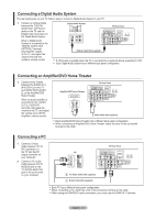
Connecting a Camcorder The side panel jacks on your TV make it easy to connect a camcorder to your TV. They allow you to view the camcorder tapes without using a VCR 1. Connect a Video Cable between the AV IN2 [VIDEO] jack on the TV and the VIDEO OUT jack on the camcorder. 2. Connect Audio Cables between the AV IN2 [R-AUDIO-L] jacks on the TV and the AUDIO OUT jacks on the camcorder. Camcorder 1 Video Cable (Not supplied) 2 Audio Cable (Not supplied) TV Side Panel Each Camcorder has a different back panel configuration. When connecting a Camcorder, match the color of the connection terminal to the cable. Connecting a DVD Player/Set-Top Box The rear panel jacks on your TV make it easy to connect a DVD player to your TV. 1. Connect a Component Cable between the COMPONENT IN(1 or 2) [Y, PB, PR] jacks on the TV and the COMPONENT [Y, PB, PR] jacks on the DVD/Set-top Box. DVD Player/Set-Top Box 2. Connect Audio Cables between the COMPONENT IN(1 or 2) [R-AUDIO-L] jacks on the TV and the AUDIO OUT jacks on the DVD/Set-top Box 2 Audio Cable (Not supplied) 1 Component Cable (Not supplied) TV Rear Panel Component video separates the video into Y (Luminance (brightness)), Pb (Blue) and Pr (Red) for enhanced video quality. Be sure to match the component video and audio connections. For example, if connecting the video cable to COMPONENT IN, connect the audio cable to COMPONENT IN also. Each DVD Player/STB has a different back panel configuration. When connecting a DVD player/STB, match the color of the connection terminal to the cable. English - 10
-
 1
1 -
2
-
3
-
4
-
5
-
6
-
 7
7 -
 8
8 -
 9
9 -
 10
10 -
 11
11 -
 12
12 -
 13
13 -
 14
14 -
 15
15 -
 16
16 -
 17
17 -
18
-
19
-
20
-
21
-
22
-
23
-
24
-
25
-
26
-
27
-
28
-
29
-
30
-
31
-
32
-
33
-
34
-
35
-
36
-
37
-
38
-
39
-
40
-
41
-
42
-
43
-
44
-
45
-
46
-
47
-
48
-
49
-
50
-
51
-
52
-
53
-
54
-
55
-
56
-
57
-
58
-
59
-
60
-
61
-
62
-
63
-
64
-
65
-
66
-
67
-
68
-
69
-
70
-
71
-
72
-
73
-
74
-
75
-
76
-
77
-
78
-
79
-
80
-
81
-
82
-
83
-
84
-
85
-
86
-
87
-
88
-
89
-
90
-
91
-
92
-
93
-
94
-
95
-
96
-
97
-
98
-
99
-
100
-
101
-
102
-
103
-
104
-
105
-
106
-
107
-
108
-
109
-
110
-
111
-
112
-
113
-
114
-
115
-
116
-
117
-
118
-
119
-
120
-
121
-
122
-
123
-
124
-
125
-
126
-
127
-
128
-
129
-
130
-
131
-
132
-
133
-
134
-
135
-
136
-
137
-
138
-
139
-
140
-
141
-
142
-
143
-
144
-
145
-
146
-
147
-
148
-
149
-
150
-
151
-
152
-
153
-
154
-
155
-
156
-
157
-
158
-
159
-
160
-
161
-
162
-
163
-
164
-
165
-
166
-
167
-
168
-
169
-
170
-
171
-
172
-
173
-
174
-
175
-
176
-
177
-
178
-
179
-
180
-
181
-
182
-
183
-
184
-
185
-
186
-
187
-
188
-
189
-
190
-
191
 |
 |
