Samsung RF31FMESBSR User Manual Ver.0.4 (English, French, Spanish) - Page 11
Setting Up - parts
 |
View all Samsung RF31FMESBSR manuals
Add to My Manuals
Save this manual to your list of manuals |
Page 11 highlights
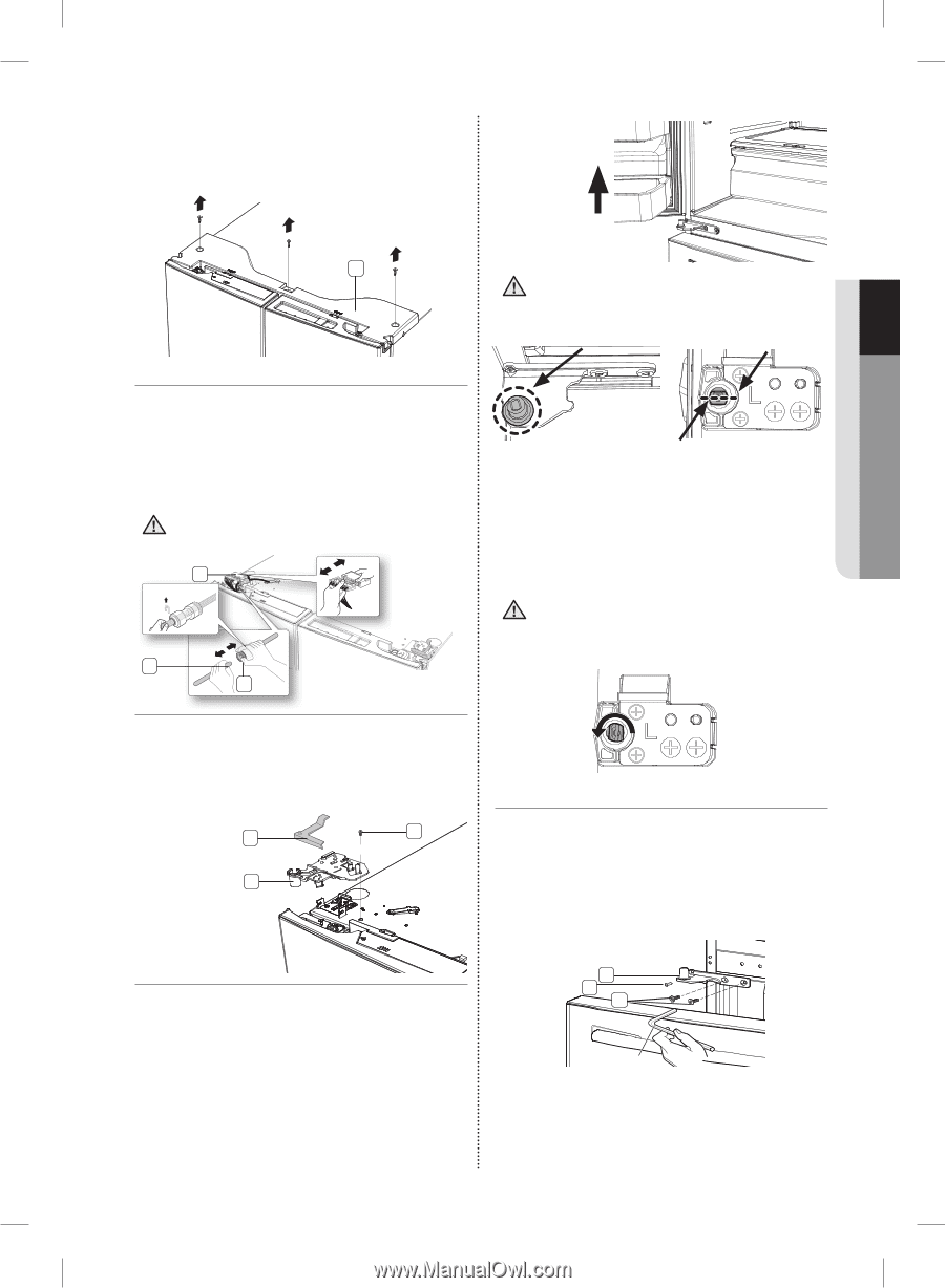
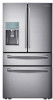
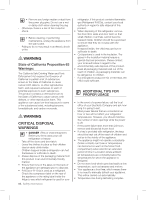
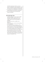
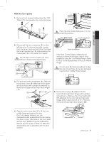
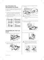
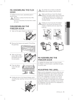
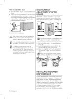
With the door opened 1. Remove the 3 screws holding down the TOP TABLE ( 1 ) and separate the connected wires. 01 SETTING UP 1 Place the door, inside facing up, on a non- CAUTION scratching surface. Door Middle Hinge Auto Closing Hinge 2. Disconnect the two connectors ( 2 ) on the left side door. To remove the water coupler from the hinge, twist and pull it from the hinge. Remove the water line ( 3 ) while pressing the marked part ( 4 ) of the water line coupler. If a red clip is on the coupler, you must CAUTION remove it before removing the tube. 2 Red Clip (1/4") 3 4 Check the direction - If the Auto Closing Hinge is aligned to be vertical as shown in the figure, align it to be parallel by using the Door Middle Hinge. (Refer to No.5 for the disassembly of the Door Middle Hinge) Do not use a flat head screwdriver to align CAUTION the Auto close Hinge. It may get damaged. Use the Door middle Hinge instead. 3. Pull and remove the hinge lever ( 5 ). Remove the ground screw ( 6 ) attached to the upper left door hinges with a philips screwdriver (+). Remove the upper left and right door hinges ( 7 ). 5 6 7 5. Remove the screw ( 8 ) attached to the lower left and right door hinges with a philips screwdriver (+). Remove the 2 hex head bolts ( 9 ) attached to the lower left and right door hinges with an allen wrench (3/16"). Remove the lower left and right door hinges ( 10 ). 4. Open the door (more than 90°), lift from the middle hinge and remove the door. - Due to its design features, you can disassemble and re-assemble the door when the door is open. (The holes in the Door Shaft and the Door Middle Hinge are deliberately tilted at specific angles so that it is difficult to disassemble and re-assemble with the door closed.) 10 8 9 Allen wrench setting up _11
-
 1
1 -
2
-
3
-
4
-
5
-
 6
6 -
 7
7 -
 8
8 -
 9
9 -
 10
10 -
 11
11 -
 12
12 -
 13
13 -
 14
14 -
 15
15 -
 16
16 -
17
-
18
-
19
-
20
-
21
-
22
-
23
-
24
-
25
-
26
-
27
-
28
-
29
-
30
-
31
-
32
-
33
-
34
-
35
-
36
-
37
-
38
-
39
-
40
-
41
-
42
-
43
-
44
-
45
-
46
-
47
-
48
-
49
-
50
-
51
-
52
-
53
-
54
-
55
-
56
-
57
-
58
-
59
-
60
-
61
-
62
-
63
-
64
-
65
-
66
-
67
-
68
-
69
-
70
-
71
-
72
-
73
-
74
-
75
-
76
-
77
-
78
-
79
-
80
-
81
-
82
-
83
-
84
-
85
-
86
-
87
-
88
-
89
-
90
-
91
-
92
-
93
-
94
-
95
-
96
-
97
-
98
-
99
-
100
-
101
-
102
-
103
-
104
-
105
-
106
-
107
-
108
-
109
-
110
-
111
-
112
-
113
-
114
-
115
-
116
-
117
-
118
-
119
-
120
-
121
-
122
-
123
-
124
-
125
-
126
-
127
-
128
-
129
-
130
-
131
-
132
-
133
-
134
-
135
-
136
-
137
-
138
-
139
-
140
-
141
-
142
-
143
-
144
-
145
-
146
-
147
-
148
-
149
-
150
-
151
-
152
-
153
-
154
-
155
-
156
 |
 |