Sharp AR-337 Service Manual - Page 15
] Simulation, Ar-287/337/ar-407/507 - specifications
 |
View all Sharp AR-337 manuals
Add to My Manuals
Save this manual to your list of manuals |
Page 15 highlights
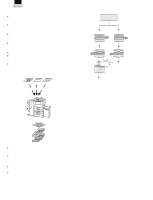
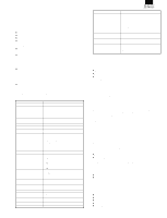
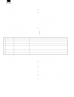
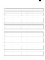
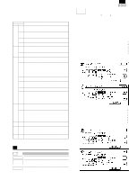
[7] SIMULATION (AR-287/337/AR-407/507) B. List Code Main Sub 8 1 2 6 7 22 1 6 26 10 12 13 22 32 44 52 50 1 2 26 51 3 61 2 4 67 18 Function (Purpose) Used to check and adjust the operation of the developing bias voltage in each print mode and the control circuit. (for OPC drum type B) Used to check and adjust the operation of the main charger grid voltage in each print mode and the control circuit. (for OPC drum type B) Used to check and adjust the transfer charger current and the control circuit. Used to check and adjust the operation of the separation charger voltage and its control circuit. Used to check the print out count of each section in each operation mode. (Used to check the maintenance timing.) Used to output the list of the setting and adjustment data (simulations, counters). Used to allow entry of the software key input for the network scanner. Used to enter the Diagnosis function key input. After completion of copier job in copier interruption during a printer job, the print job is resumed in synchronization with the auto clear timer (key operation) setup time [10-240]. By making the setup below, the print job is resumed in 0 sec. (However, the auto clear function is enabled with the setup time of key operation. Also, this simulation and auto clear are not synchronized.) Used to set the specification (language display) for the destination. (Excluding the Japan models.) When the variable speed fan motor is in the ready state and the process temperature is in the range of 36° - 45°, the PWM duty is set in percentage. Used to set the model of the unit which is connected to the SCSI I/F of ICU PWB. Used to set whether white paper discharge count up is performed or not. ("White paper" means insertion paper in the OHP insertion paper mode (without copy), cover paper in the cover paper insertion mode (without copy)/back cover, and white paper in the duplex exit mode (CA etc.).) Used to adjust the copy image position and the void area (image loss) on the print paper in the copy mode. (The same adjustment can be made with SIM 50-2 (simple method).) Used to adjust the copy image position and the void area (image loss) on the print paper in the copy mode. (Simple adjustment) (This simulation allows the same simulation with SIM 50-1 more simply. ) Used to set the folding margin of center binding. Used to set the clutch OFF time. (AR-507 Europe and U.K. only) Used to adjust the scanner (exposure) laser power (absolute value) in the copy mode. Used to adjust the scanner (exposure) laser power (absolute value) in the printer mode. (For Photoconductor type B) Used to clear the application data area of the Network Scanner of the Flash ROM. C. Details of simulations AR-287/337 AR-407/507 Operation/ (The developing bias output voltage of each print mode Procedure can be adjusted and checked.) 1. Select the print mode with [] key and [¯] key. 2. Enter the adjustment value with the 10-key pad. 3. Press the [EXECUTE] key. The [EXECUTE] key is highlighted, the adjustment value entered in procedure 2 is set, and the voltage corresponding to the set value is supplied. After supplying the voltage for 30 sec, the [EXECUTE] key returns to the normal display. If the [EXECUTE] key is pressed while the voltage is supplied, the voltage output is stopped and the [EXECUTE] key returns to the nor- mal display. AUTO : Auto mode * (500) (-500V ±5V) CHARA : Character mode * (500) (-500V ±5V) CHARA PHOTO : Character/Photo mode * (500) (-500V ±5V) PHOTO : Photo mode * (500) (-500V ±5V) PRINTER : Printer mode * (500) (-500V ±5V) PLUS : Cleaning mode * (150) (+150V ±5V) Developing bias voltage * ( ): Default (AR-287/337/407) (AR-507) AUTO CHARA CHARA PHOTO PHOTO PRINTER PLUS * ( ): Default : Auto mode * (415) (-425V ±5V) : Character mode * (490) (-500V ±5V) : Character/Photo mode * (490) (-500V ±5V) : Photo mode * (490) (-500V ±5V) : Printer mode * (490) (-500V ±5V) : Cleaning mode * (165) (+150V ±5V) Developing bias voltage 8 8 -1 Purpose Function (Purpose) Section Adjustment/Operation test/check Used to check the operation of the developing bias voltage in each print mode and its control circuit. (For OPC drum type B) Process (OPC drum, developing unit, transfer, cleaning) section 7 - 51 3/13/2000
-
 1
1 -
2
-
3
-
4
-
5
-
6
-
7
-
8
-
9
-
 10
10 -
 11
11 -
 12
12 -
 13
13 -
 14
14 -
 15
15 -
 16
16 -
 17
17 -
 18
18 -
 19
19 -
 20
20 -
21
-
22
-
23
-
24
-
25
-
26
 |
 |
