Sharp AR-337 Service Manual - Page 17
Operation data output/Check Display/Print - digital imager
 |
View all Sharp AR-337 manuals
Add to My Manuals
Save this manual to your list of manuals |
Page 17 highlights
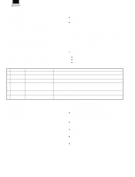
8 -7 Purpose Adjustment/Operation test/check Function Used to check and adjust the operation of the separa(Purpose) tion charger voltage and its control circuit. Section Image process (Photoconductor/ Developing/Transfer/ Cleaning) Others Operation/ The separation charger output voltage in printing the Procedure front and the back of paper can be adjusted and checked. 1. Select the print mode with [] key and [¯] key. 2. Enter the adjustment value with the 10-key pad. 3. Press the [EXECUTE] key. The [EXECUTE] key is highlighted, the adjustment value entered in procedure 2 is set, and the voltage corresponding to the set value is supplied. After supplying the voltage for 30 sec, the [EXECUTE] key returns to the normal display. If the [EXECUTE] key is pressed while the voltage is supplied, the voltage output is stopped and the [EXECUTE] key returns to the normal display. FROMT MODE: Front surface print (with the paper feed tray and manual paper feed tray) BACK MODE: Back surface print (with duplex paper feed) (AR-287/337) (AR-407) Item Operation/ Procedure Counter AR-287/337 AR-407/507 nnnnnnnn : Counter value 22 - 6 Purpose Operation data output/Check (Display/Print) Function Used to output the list of the setting and adjustment (Purpose) data (simulations, counters). Item Data Adjust/Setting data Operation/ Procedure When installing or servicing, execute this simulation to print and store the adjustment values and setting data for use in the next servicing. (Memory trouble, PWB replacement, etc.) In this case, the print conditions can be set optionally. 1. Select the setup item. (The selected item is highlighted.) 2. Set the item and conditions with the 10-key pad. 3. Press the [EXECUTE] key to print various data. A: Paper feed mode 1: Manual paper feed 2: Upper paper feed tray 3: Lower paper feed tray 4: Desk upper paper feed tray 5: Desk middle paper feed tray 6: Desk lower paper feed tray 7: Large capacity paper feed tray (AR-507) 26 22 22 - 1 Purpose Function (Purpose) Operation data output/Check (Display/Print) Used to check the print out count of each section in each operation mode. (Used to check the maintenance timing.) 26 - 10 Purpose Setting Function Used to allow entry of the software key input for the (Purpose) network scanner. Item Operation Operation/ 1. After entering the sub code of the simulation, enter Procedure the software key in the obtained frame of "NEW." 2. When the obtained number is entered with the 10-key (max. 9 digits), the entered number is displayed in the frame of "NEW." After entering the number, press the [OK] key, and the entered number is stored. 3. Reset with the CA key, and the scanner function is enabled. * Only when SCSI (20 channels/NS1) setup is completed. If the scanner key input is made without setup, it is rejected. 4. Special note 7 - 53 3/13/2000
-
 1
1 -
2
-
3
-
4
-
5
-
6
-
7
-
8
-
9
-
10
-
11
-
 12
12 -
 13
13 -
 14
14 -
 15
15 -
 16
16 -
 17
17 -
 18
18 -
 19
19 -
 20
20 -
 21
21 -
 22
22 -
23
-
24
-
25
-
26
 |
 |
